|
|
BRITISH AUTOMOTIVE |
|
www.mgbmga.com MGTD Articles |
Technical Information (MGB 4)
Composite Leaf Springs
Last Modified - 01/28/03
MGB4(7)
The following components are designed to be used when your MGB rear ride height needs to be increased. Ideal for both OEM and Composite Spring applications.There are two separate kits available.
1. Chrome bumper vehicles (prior to 1974.5)
2. Rubber bumper vehicles (1974.5 on)
These complete kits are shown in the following images:
1. PART # RSARHK/CB 2. PART # RSARHK/RB
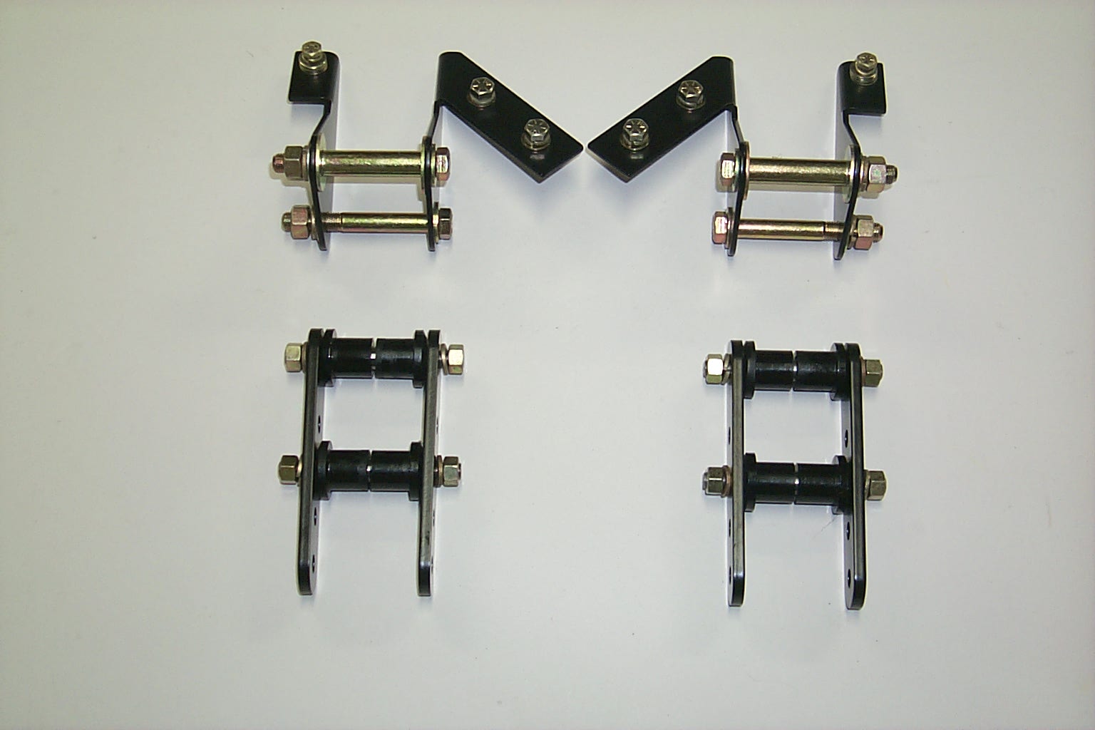
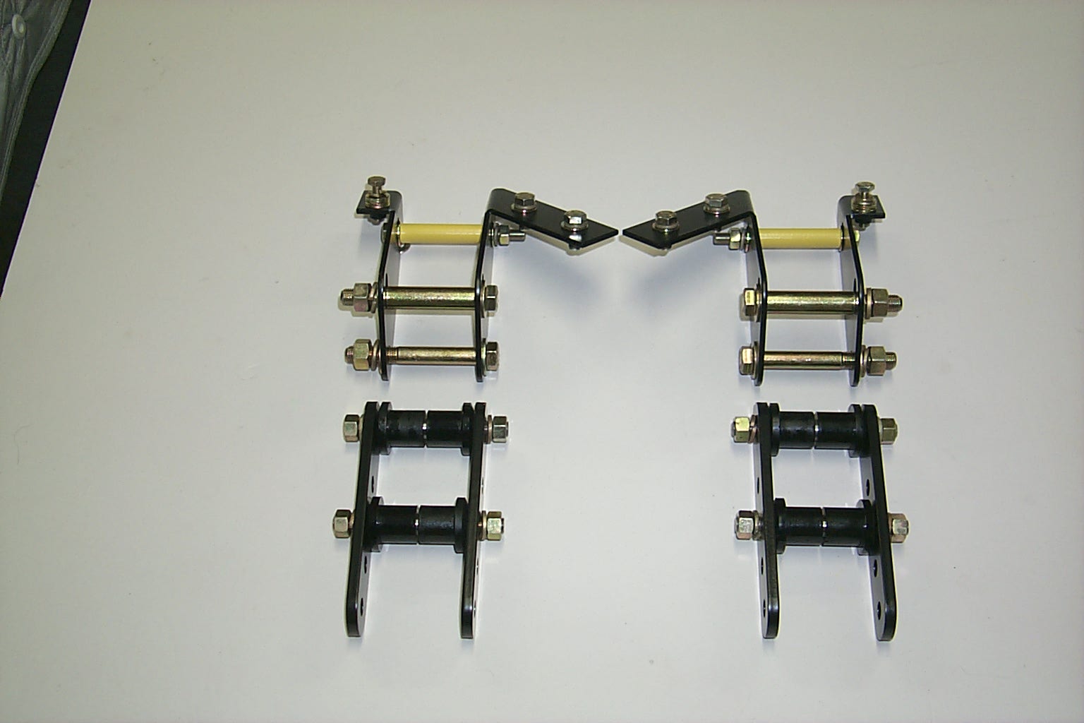
P0002482 P0002523
RSARHK/RB kit consists of two separate kits as follows:
PART # RRHAFBK/RB PART # RRHASK
P0002520 SPRING SHACKLES 72. jpg
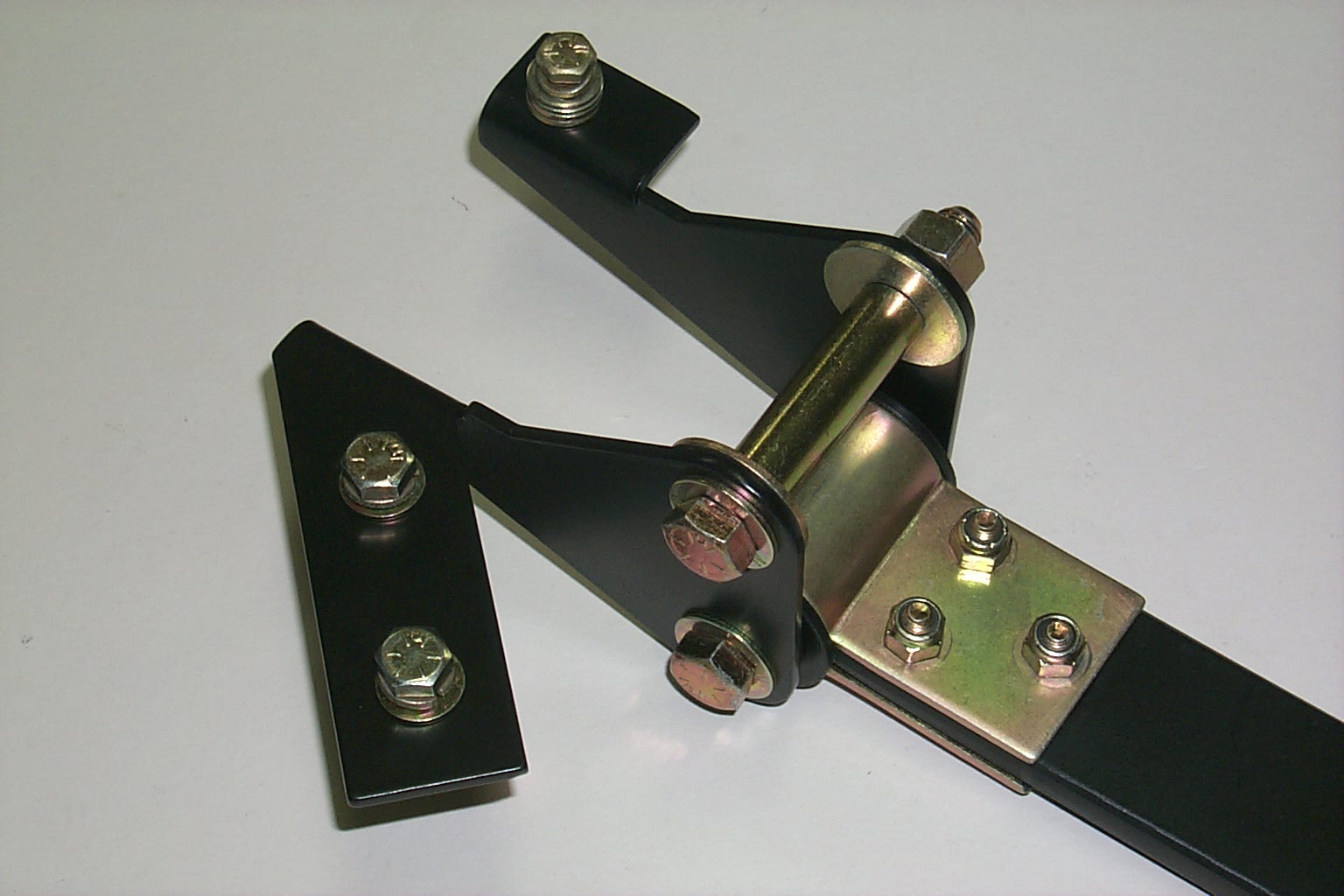
RIGHT HAND VIEW
OEM STEEL SPRING APPLICATION.
All MGB's fitted with original rear leaf springs will experience "spring sag" at some stage during the vehicle's lifetime. The usual remedy is to simply replace the spring assemblies. Unfortunately, modern steel leaf springs seem to be more prone to this sag then their predecessors. Replacing OEM steel springs may become an ongoing operation.
Installing part number RRHASK may indeed be a better alternative than actually replacing the springs themselves. Further, this product could be installed in conjunction with replacement road springs.
RRHASK was designed with the OEM spring shackle measurements in mind, plus the ability to allow the rear ride height to be increased in increments of approximately 1/2" for a maximum of 1". This may be an attractive purchase for those MGB owners who wish to take long trips, yet can not bear to see the backend of the vehicle dragging on the ground when loaded with luggage, spare parts and tools etc. Relatively simple job to change your rear ride height as you desire.
Further increases in rear vehicle ride height (approximately 3/4") can be achieved by the installation of part numbers RRHAFBK/CB or RRHAFBK/RB respectively.
NOTE: Bracket kits RRHAFBK/CB & RRHAFBK/RB are also used as part of British Automotive's traction control arm kit. If you intend to fit this device, or indeed you have already fitted this device to your vehicle, be aware that these kits will not work in the manner prescribed above.
NOTE: Installation of this kit may effect the way your vehicle handles. Remember INCREASING vehicle rear ride heights INCREASES the roll center heights and therefore vehicle UNDERSTEER.
COMPOSITE SPRING APPLICATION
Unfortunately, due to the design of the composite spring blade, part number RRHASK must be used in conjunction with part numbers RRHAFBK/CB or RRHAFBK/RB. Use complete kit part numbers RSARHK/CB or RSARHK/RB for this application.
Please do install part number RRHASK alone. If so attempted, the rear section of the spring blade will be subject to undue stresses.
Ride height changes are outlined in OEM STEEL SPRING APPLICATION.
NOTE: Installation of this kit may effect the way in
which your vehicle handles. Remember INCREASING rear ride heights
INCREASES the roll center and rear wheel UNDERSTEER.
RIDE HEIGHT KIT CONTENTS
PART # RRHAFBK/CB PART# RRHAFBK/RB
2 - Inner L/H & R/H support brackets 2 - Inner L/H & R/H
support brackets
2 - Outer L/H & R/H support brackets 2 - Outer L/H & R/H
support brackets
2 - Spacer tubes (7/16" ID) 2 - Spacer tubes (7/16" ID)
4 - 7/16" X 3.5" SAE bolts 4 - 7/16" X 3.5" SAE
bolts
4 - 7/16" SAE nuts 4 - 7/16" SAE nuts
4 - 7/16" lockwashers 4 - 7/16" lockwashers
8 - 7/16" SAE flat washer 4 - 7/16" SAE flat washer
4 - 5/16" X 1" SAE bolts 4 - 5/16" X 1" SAE bolts
8 - 5/16" SAE flat washer 16 - 5/16" SAE flat washer
4 - 5/16" lockwasher 6 - 5/16" lockwasher
2 - 1/4" X 1' SAE bolts 2 - 1/4" X 1" SAE bolts
6 - 1/4" SAE flat washer 6 - 1/4" SAE flat washer
2 - 1/4" lockwasher 2 - 1/4" lockwasher
2 - 7/16" SAE spacer washers (large) 2 - 5/16" X 3.5" SAE
bolts
2 - 5/16" Spacer tubes (5/16" ID)
2 - 5/16" SAE nuts
LIST PRICE $85.10
PART # RRHASK
4 - Shackle pins .500" OD
4 - Shackle pin links
8 - 3/8" SAE nuts
8 - 3/8" lockwashers
8 - Delrin bushings
8 - Polyurethane bushings (95 Durometer scale)
1 - 3/8" SAE jam nut
1 - Lube
LIST PRICE $89.95
----------------------------------------------------------------
INSTALLATION INSTRUCTIONS
PART # RRHAFBK/CB
These instructions should be read in conjunction with the appropriate section of the workshop manual i.e. rear road spring replacement.
When working with the drivers' side (left-hand drive) you will need to remove the rear section of the exhaust system.
NOTE: FOR EASIER INITIAL INSTALLATION USE FLAT WASHERS ONLY. INSTALL THE PROVIDED LOCKWASHERS UPON FINAL ASSEMBLY. ALL JAGGED EDGES, CAUSED BY DRILLING, MUST BE FILED FLUSH. WORK ON ONE SIDE AT A TIME. START ON THE RIGHT HAND SIDE FIRST.
1. Using your workshop manual as a guide, remove the front spring mounting bolt, then lower the spring down to clear the road spring support.
2. Locate inner and outer support brackets. Insert upper mounting bolt, spacer tube and large washers. Finger tighten nut. Align brackets so that they are vertical and also horizontal. Use a small "level" for this purpose. Tighten nut to prevent bracket movement.
3. Mark, locate and pilot drill (1/8") the upper floor panel
attachment holes. Be sure to
pull back carpet to avoid damage. Remove support brackets.
4, From inside the vehicle locate the 3 1/8" pilot holes. Remove sound-deadening material then; drill the outer hole to 17/64". Drill the remaining 2 pilot holes to 21/64".
5. Reinstall both support brackets along with hardware. Recheck brackets for vertical and horizontal alignment. Install upper mounting hardware followed by support bracket hardware. Snug tighten hardware.
NOTE: If the floor pan is not flush with the support brackets use provided 5/16" and 1/4" flat washers for spacing.
6. Install and snug tighten front spring eye mounting hardware.
NOTE: Final tightening of all hardware must be done with the vehicle on the ground.
-------------------------------------------------------
PART # RRHAFBK/RB
These instructions should be read in conjunction with the appropriate section of the workshop manual i.e. rear road spring replacement.
When working with the drivers' side (left-hand drive) you will need to remove the rear section of the exhaust system.
NOTE: FOR EASIER INITIAL INSTALLATION USE FLAT WASHERS ONLY. INSTALL THE PROVIDED LOCKWASHERS UPON FINAL ASSEMBLY. ALL JAGGED EDGES, CAUSED BY DRILLING, MUST BE FILED FLUSH. WORK ON ONE SIDE AT A TIME. START ON THE RIGHT HAND SIDE FIRST.
1. Using your workshop as a guide, remove the front spring mounting bolt, then lower the spring down to clear the road spring support.
2. Position inner and outer support brackets. Insert upper mounting bolt and finger tighten nut. Align brackets so that they are both vertical and horizontal. Use a small "level" for this purpose. Tighten nut to prevent support bracket movement.
3. Mark, locate and pilot drill (1/8") the upper floor panel
attachment holes. Be sure to pull back interior carpet to avoid damage.
Remove support brackets.
4. From inside the vehicle locate the 3 1/8" pilot holes. Remove sound-deadening material then; drill the outer hole to 17/64". Drill the remaining 2 pilot holes to 21/64".
5. Reinstall support brackets along with hardware. Recheck brackets for both vertical and horizontal alignment. Snug tighten upper mounting hardware followed by support bracket hardware.
NOTE: If the floor pan is not flush with the support brackets, use the provided 5/16" and 1/4" flat washers for spacing.
6. Install and snug tighten front spring eye mounting hardware.
7. Scribe inner support bracket elongated hole on to the road spring support abutment.
8. Using the smallest chuck sized pistol drill or right angle drill available, pilot drill 1/8" hole in the center of the elongated hole and through the inner spring support abutment only. Change drill to 21/64".
9. Drill out the aforementioned hole, on and through the outer spring support abutment. Keep drill bit as straight as possible. Deburr holes.
NOTE: Depending upon the size of the drill, it may be more convenient to remove the inner support bracket.
10. Install 5/16 X 3.5" SAE bolt and nut, noting that the spacer tube is flanked either side with a 5/16" flat washer. Snug tighten hardware.
NOTE: Final tightening of all hardware must be done with the vehicle on the ground.
-------------------------------------------------------------
PART # RRHASK
Remember this kit can be individually fitted to OEM steel road springs only.
Composite springs: requires fitting in conjunction with PART # RRHAFBK/CB or PART # RRHAFBK/RB
These instructions should be read in conjunction with the appropriate section of the workshop manual i.e. rear spring shackle bushing replacement.
1. Remove all rust and scale from the following:
A. Rear road spring eyes.
B. Upper shackle bushing body recesses.
C. Shackle pins
D. Shackle pin end plates.
2. Lubricate the surfaces of the polyurethane bushings, including shackle pins.
3. Insert pins and attach shackle links.
4. Snug tighten hardware.
NOTE: Final tightening of all hardware must be done with the vehicle on the ground.
For additional information select from one of the following categories:
MGB4(1)...An Introduction to Composite Springs
MGB4(3)...MGB Vehicle Lean Problems
MGB4(4)...MGB Anticipated Ride Heights