|
|
BRITISH AUTOMOTIVE |
|
www.mgbmga.com MGTD Articles |
Technical Information (MGB 16C)
MGB OEM Offset Rocker Pedestals with Roller Rockers
Last Updated 2/28/07
In technical article MGB16, we discussed the benefits of using roller rockers over OEM rocker arms. One of those benefits is being able to increase the rocker ratio over and above the OEM ratio. However, this method of increasing the valve lift will increase the working angle of the pushrod, resulting in possible pushrod contact within the cylinder head bore. This is more so when using aftermarket 5/16”tubular pushrods.
Increased rocker arm ratios normally require a reduced distance between the rocker arm bore centerline and the rocker adjusting screw ball centerline. Since, the OEM rocker pedestal bore centerline is fixed to that of the valve stem centerline, this is the most convenient method of increasing the rocker arm ratio.
While developing British Automotive’s AVT system, we decided to tackle this problem in a different manner. Through calculations, we concluded that the OEM rocker pedestalbore centerline could be safely offset towards the pushrod side by 0.070”. In the AVT system, we actually had new rocker pedestals manufactured with a 0.110” centerline offset.
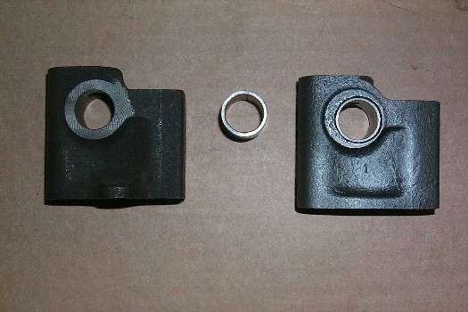
The following image shows the OEM rocker shaft pedestal, the OEM rocker arm bushing and the modified OEM rocker shaft pedestal with the OEM rocker arm bushing inserted.
Rather than increase expenses by having new rocker shaft pedestals manufactured, we decided to cut costs by modifying the OEM rocker pedestals instead. The 0.070” offset we achieved on the pedestals allowed us to increase the rocker arm roller contact centerline distance by the same amount. A simple reposition of the roller pin-mounting bore was all that was required. A new roller rocker ratio of 1.58:1 was established (1.428” - .905” = 1.58:1).
With the Harland Sharp roller rocker design, we are limited as to the rocker roller centerline position. For rocker arm structural integrity, this was limited to 1.443” from the centerline of the rocker arm bore. With our AVT system two roller rocker ratios were established. 1.55:1 (1.443” - .931” = 1.55:1) and 1.59:1 (1.443” - 0.905” = 1.59:1) with the 1.55:1 version being assembled to the engine. Also, for better valve train geometry, we reduced the roller OD to 0.541”. Our current production roller rockers 1.55:1 (1.358” - 0.876” = 1.55:1) use this same size roller OD and use the stock OEM rocker pedestals.
How did we modify the existing OEM rocker pedestals, well here goes;
At right angles to the rocker pedestal base, machine 0.025” from both faces of each rocker pedestal, this will ensure that the rocker arm spacers (0.025”) will have a smooth surface contact area. Reference .070” from the center line of the original rocker shaft bore, machine out to 0.7485” to 0.7495”. This machining operation must be accurate; the horizontal plane of the new bore should match that of the pedestal base.
Press and centralize new OEM style rocker arm bushings (Moss Motors part number 330-150) into the rocker shaft pedestals. Be sure that the oil groove within the bushings is at the bottom.
Your next operation is drill out the rear pedestal oil feed hole and the rocker shaft locating screw hole. Use 5/32” drill bit for the oil feed hole and number Q (0.332”) for the locating screw hole. However, use the Q drill to centralize and rotational indent this location first. Use the 5/32” drill bit for the pilot hole then you can follow this up with the Q drill bit. Pass a 3/8”SAE (24TPI) thru the top of the pedestal and thru the rocker shaft bushing.
Your final operation will be to hone out the bushings to 0.6250” to 0.6260”. Be sure to check the OD of your rocker shaft before using these measurements. The rocker shaft OD should be 0.0624” to 0.0625”.
You will notice that the rocker shaft as now taken up a different rotational position within the rocker pedestal, this does not effect the oil feed to the rocker shaft or rocker arms. This new offset oil feed hole, within the bushing, channels oil into the bushing trough and is directed through the rocker shaft oil feed hole. This also holds true for the roller rocker arms as well. So, be sure that when pressing the bushing into the pedestal, you have this oil trough at the bottom.
Choosing the correct rocker arm ratio, in conjunction with a particular camshaft lobe lift, is critical. Overstressed valve train components will ruin your engine rebuild in a hurry. I would like to present to you information compiled during my many years of rebuilding MGA and MGB engines, while using 1.55:1 Harland Sharp roller rockers.
We will concentrate on giving you information that will cover street use and street performance use only. Valve spring information covers dual spring applications as supplied from the factory and Moss Special Tuning. Also, we have concentrated on camshaft lobe lifts of 0.280” and greater.
The following information is actual data from numerous engine assembly worksheets using various cam profiles.
| Camshaft Lobe Lift | Theoretical Valve Lift | Actual Valve Lift (Zero Lash) |
|---|---|---|
| 0.280” | 0.280” x 1.55 = 0.434” | 0.422” (0.280”) = 1.51:1 |
| 0.280” | 0.280” x 1.55 = 0.434” | 0.426” (0.280”) = 1.52:1 |
| 0.281” | 0.281” x 1.55 = .4355” | 0.418” (0.281”) = 1.49:1 |
| 0.281” | 0.281” x 1.55 = 0.4355” | 0.421” (0.281”) = 1.50:1 |
| 0.287” | 0.287” x 1.55 = 0.4448” | 0.426” (0.287”) = 1.48:1 |
| 0.287” | 0.287” x 1.55 = 0.4448” | ”0.428” (.287”) = 1.49:1 |
| 0.288” | 0.288” x 1.55 = 0.446” | 0.431” (0.288”) = 1.50:1 |
| 0.290” | 0.290” x 1.55 = 0.4495” | 0.439” (0.290”) = 1.51:1 |
| 0.292” | 0.292” x 1.55 = 0.4526” | 0.446” (0.292”) = 1.53:1 |
| 0.294” | 0.294” x 1.55 = 0.4557 | 0.446” (0.294”) = 1.52:1 |
As you can see we were never able to duplicate the actual 1.55:1 rocker arm ratio (see end column), this could be due to slight measuring errors (I’d like to think not). However, I feel that different valve spring installed heights, resulting in rocker arm geometry changes, and pushrod angles also contributed to this end result.
Moving on ........ Relative to the above information, the valve spring installed height plays a very important part, for this establishes valve seat and valve open spring pressures, as well as determining the amount of acceptable valve lift without the actual valve spring becoming coil bound, or even the upper spring retaining collar contacting the top of the valve guide. For established safety norms to prevent valve spring coil bind, allow 0.010” clearance for every working coil. To prevent spring retaining collar contact with the valve guide allow 1/16” to 1/8” clearance.
On the single valve spring set up used on the 18V series engine, I have always upgraded to the dual valve spring set up as used on the 18G-18V engines. The factory parts manual showed two different dual valve spring sets for the MGB engine. However, it appears the only difference between these two sets is the inner spring. The MGA1622 and MGB 18G/18GA engines fitted an oil deflector that fitted inside the inner spring which, I believe, accounted for the difference in part numbers. 18G/18GA inner spring 1H723 outer spring 1H1111 (factory suppression to 12H1679) 18GB-18V inner spring 12H176 (50 lbs.) outer spring 12H1679 (110 lbs.). AE was the primary supplier of these valve spring sets, which showed 18G/GA using VSP621P spring set, and VSP5054P spring set for the 18GB-18V engines.
“XRN Engineering LTD” UK is now the primary manufacturing source for valve spring sets, these are marketed under the “County” brand name. The correct “County” part number is CVS637K. Moss Motors part number is 423-430. This valve spring set is manufactured to the OEM specifications above.
Increasing valve spring seat pressures will raise the valve train crash speed r.p.m. Using engine data from the MGB workshop manual, this was 6200 RPM with a valve spring seat pressure of approximately 100 lbs. to 104 lbs. To achieve this, the factory specifications required an outer valve spring fitted length of 1.5625” and an inner valve spring fitted length of 1.4375” (based upon new valve seats and new valves). Facing valves and cutting valve seats will increase this figure and lower the valve spring seat pressure.
Valve spring specifications given for full valve lift 0.3645”, along with the OEM camshaft lobe lift specification of 0.250”, were: outer valve spring 117 LB, inner valve spring 48 lbs. to 52 lbs. for a total of 165 lbs. to 169 lbs. Indicated rocker arm ratio 0.3645” divided by 0.250” = 1.458:1. In numerous OEM data sheets, I have seen 1.426:1 ratios quoted. Personally, I have never been able to duplicate either of these two ratios when using OEM rocker arms. I believe this shows how extremely important valve train geometry is in arriving at any rocker arm ratio calculations.
Recently, I had the opportunity to check out valve spring set CVS637K (Moss Motors 423-430). The following data is not computerized data, but achieved with the use of a micrometer and vernier gauge.
Outer valve spring free height 2.220”. Coil bound. 0.985”. Working length 1.235”. Spring rate 110 lbs. Active coils 4.5. Coil bound safety margin + 0.045” = 1.030”.
Inner valve spring free height 2.000”. Coil bound. 0.995”. Working length 1.005”. Spring rate 50 lbs. Active coils 6.5. Coil bound safety margin + 0.065” = 1.060”
We may be off a few thousands either way, but this should not deter you from using this data in rebuilding your cylinder head.
Working from my old engine rebuild data sheets, I am going to use an installed valve spring height of between 1.5” to 1.6” in 0.025” increments. At 1.5” = 108 lbs. 1.525” = 104 lbs. 1.550” = 100 lbs. 1.575” = 96 lbs. 1.600” = 92 lbs. Usually, higher valve spring seat pressures are recommended with higher camshaft lobe lifts, however, but not as critical as valve/spring fully open pressures.
NOTE: We do not use seperate calculations for the inner spring. Since, this spring is part of the dual valve spring set up; we do all our calculations as a combined assembly. With the inner valve spring free height being approximately 0.220” shorter than the outer valve spring, we know that if the calculations for coil bound conditions are OK with the outer valve spring, then the inner valve spring is good also.
For our maximum valve spring allowable lift, we must subtract the valve spring coil bound safety height (1.030”) from the valve spring assembly installed height (1.500”) = 0.470” maximum lift, the result for an installed height of 1.600” would be 0.570”. However, unless some serious investment in cylinder head modifications are anticipated, this 0.470” let alone 0.570” is going to bring no benefit whatsoever. Besides, valve cap to valve guide contact issues would probably arise at these valve lifts.
For street performance, increasing cam lobe lifts seems to be the norm for camshaft regrinders. However, since the “B” series engine has small OD (0.812”) lifters, problems can occur with, what I call, excessive camshaft lobe lifts. In order to attain increases in camshaft lobe lifts, regrinders reduce the lobe heel diameter. Depending upon the amount of lift ground into the camshaft lobe, the lobe could act like a cutting knife as the lobe nose intersects the lifter edge. Also, since high lift camshaft lobes require increased valve spring pressures, lifter to camshaft lobe nose interface contact is compromised. I would go with around 0.280” cam lobe lift, this applies to both intake and exhaust valves. Do the offset rocker pedestal, use 1.58:1 roller rockers, this should give you around .4424” theoretical lift less the running valve clearance. If you want more valve lift then the roller rockers could be modified to the following 1.428 - 0.876 = 1.63:1. However, using this ratio, in all probability, would require cylinder head pushrod tube elongation to prevent pushrod contact.
Trying to find a reground camshaft with lobes lifts of around 0.280” could be difficult. However, Kent Cams provide a 714 (mild road) and 715 (fast road) regrind with both having 0.264” lobe lift. D. Elgin Racing Cams USA (415) 364-2187 have numerous regrinds available meeting this criteria.
Before roller rockers were introduced to the market, most camshaft regrinders were working with the OEM rocker arm ratio of around 1.426:1. Reprofiling camshaft lobes to get more lift at the valve was the norm. At present, I don’t know of any camshaft manufacturer, or regrinder that supplies custom profled camshafts to be used with higher roller rocker ratios, higher that is than the OEM 1.426:1.