|
|
BRITISH AUTOMOTIVE |
|
www.mgbmga.com MGTD Articles |
Technical Information (MGB 16)
ROCKER ARMS (OEM AND ROLLER
ROCKERS)
Last Modified - 3/18/01
The following series of tests were carried out to determine what effects different valve springs #'s had upon various IRAR's (indicated rocker arm ratio(s)) and the resulting ERAR's (effective rocker arm ratio(s)). We were also looking to see what changes occurred in the valve timing sequences and consequently the valve open duration period due to these various ERAR's. Also, during these tests, we were able to carry out comparison checks between the OEM style rocker arm (A) and British Automotive's roller rocker arms 1.5:1 (B) , 1.55:1(C)and 1.6:1(D) ratios. Valve timing sequences and duration recorded at .001" after valve open and .001" before valve closed, camshaft lift .292". Tubular 5/16" pushrods were used throughout all tests.
Test 1: Iskenderian soft valve springs 1# were used and the valve clearance set to zero to establish a test basis. IRAR's were calculated for every .025" of camshaft lift until maximum valve lift was achieved.
Rocker Type |
Max. Valve Lift |
Camshaft lift |
IRAR |
A - OEM rocker |
.422" |
.292" |
1.445:1 |
B - 1.5:1 roller |
.441" |
" |
1.5:1 |
C - 1.55:1 roller |
.455" |
" |
1.56:1 |
D - 1.6:1 roller |
.470" |
" |
1.6:1 |
Conclusions: Because the valve spring 1# had no influence, these rocker arm ratios could be regarded as the true IRAR's. Roller rocker IRAR's stayed constant throughout the entire valve lift, while the OEM rocker showed increasing IRAR's for every .025" of camshaft lift throughout the full valve lift sequence (see Conclusions - OEM rocker arm).
Test 2: Valve spring substitution, single valve spring 140#, valve spring seat pressure 72#, valve clearance .010", maximum valve lift includes initial .010" clearance.
Rocker Type |
Max.Lift Cam Lift |
ERAR |
Valve |
Timing |
Duration |
A - OEM |
.397" |
.292" |
1.359:1 |
60 deg. - 36 deg. |
276 deg. |
B - 1.5:1 |
.416" |
" |
1.425:1 |
58 deg. - 34 deg. |
272 deg. |
C - 1.55:1 |
.431" |
" |
1.476:1 |
59 deg. - 34 deg. |
273 deg. |
D - 1.6:1 |
.442" |
" |
1.514:1 |
59 deg. - 36 deg. |
275 deg. |
Test 3: Valve spring substitution, dual valve spring 216#, valve spring seat pressure 115#, valve clearance .010", maximum valve lift includes initial .010" valve clearance.
Rocker Type |
Max. Lift |
Cam Lift |
ERAR |
Valve Timing |
Duration |
A - OEM |
.397" |
.292" |
1.359:1 |
58 deg. - 32 deg. |
270 deg. |
B - 1.5:1 |
.397" |
" |
1.414:1 |
57 deg. - 32 deg. |
269 deg. |
C - 1.55:1 |
.426" |
" |
1.459:1 |
57.5 deg - 33 deg. |
270.5 deg. |
D - 1.6:1 |
.443" |
" |
1.517:1 |
58.5 deg - 33.5 deg. |
272 deg. |
Test 4: Tubular 5/16" pushrods were replaced with OEM solid type and Test 3 repeated with identical results
CONCLUSIONS & COMMENTS
OEM rocker arm: OEM rocker arm: We mentioned in Conclusions (Test 1) that the OEM rocker arm IRAR was constantly increasing throughout the full valve lift. This can be explained as follows: the center line of the rocker arm to the valve stem center line changes as the rocker end tip sweeps across the valve stem face moving the center line further outwards on the rocker arm which increases the IRAR. Also, we are creating "dwell" with this rocker arm sweeping motion, which results in increased duration readings (Test 2), especially when compared with roller rockers. This shows how important it is to have the correct rocker arm tip end profile. One would have assumed that by using a roller rocker arm with a greater IRAR that we would have anticipated earlier valve opening sequences when compared to the OEM rocker arm design, however, this was not so. After careful examination of the test results and components, we came to the conclusion that increased pushrod angles do effect valve opening sequences and valve open duration. We noticed that the design of the roller rocker dictated a different horizontal rocker arm position (valve closed), and when combined with the shorter distance between the rocker arm adjusting screw ball and the rocker shaft center line (increased IRAR), this had sufficiently changed the pushrod angle so as to effect the valve opening position.
Roller rockers: Roller rocker IRAR's stay constant throughout the full valve lift because the center line of the roller stays constant and only its contact with the valve stem center line changes. Increases in the roller rocker IRAR, when used with the same spring #, will result in only slight increases in valve timing and valve open duration readings
OEM pushrod: We were anticipating that in Test 4 we might see some changes in readings due to pushrod deflection and pushrod misalignment angles; although this was not the case, we know that dynamic deflection undoubtedly takes place at high engine RPM's. If we look at this pushrod misalignment angle, we can see that this is due to the different vertical center lines of 1 - the camshaft lobe, and 2 - the rocker arm adjusting screw ball. This vertical misalignment results in bending loads being applied to the pushrod, and these loads will increase with increased valve spring #'s and engine RPM. Therefore, the recommendation is to use 5/16" chrome moly or tempered chrome moly tubular pushrods only. Be sure there is no contact between the pushrod and the cylinder head pushrod guide tube hole, the pushrod must be allowed to rotate without interference. This problem will become more apparent when using increased rocker arm IRAR's or increased camshaft lobe lifts. To remedy this situation, offset grinding of the cylinder head pushrod guide tube hole will be required or, as we like to do, bore out these guide tube hole to .660". If you should decide upon the latter, then be aware that premature break through can occur if you over enlarge the cylinder head intake ports in the area of the guide tube hole.
The leverage factor produced by various rocker arm IRAR's, and their relationship with valve spring #'s, are often overlooked. By increasing the rocker arm IRAR's we are also increasing valve spring #'s during the valve opening sequence, peaking at full valve lift. The valve spring # is subject to a multiplication factor to that of the rocker arm IRAR, and this valve # is exactly what the cam lobe sees, especially the camshaft nose at peak valve lifts, at low to moderate engine RPM speeds. As engine speed increases, the camshaft lobe inertia forces overcome valve spring #'s with the camshaft lobe nose seeing reduced loads.
Let's take a look at this rocker arm leverage factor, or as I would like to say, multiplication factor.
Example 1: OEM rocker arm (1.445:1 IRAR),
valve spring 140#, max.valve lift .397", valve spring seat 72#, valve spring
open # = 72# + (.397" x 140#) .
= 72# + 56# .
= 128#
Load # on cam lobe = IRAR x 128#
= 1.445
x 128#
= 185#.
Load # at 1000 Eng. RPM divided by 2 = 500 camshaft RPM
Load # at 500 cam RPM = 500 x 185# (1
lobe)
= 92,500# Load # at 500 cam RPM (8 lobes)
= 92,500# x 8
=740,000#
Example 2: Roller rocker arm (1.6:1 IRAR,
valve spring 140#, max.valve lift .442", valve seat pressure 72#, valve spring
open # = 72# + (.442" x 140#)
= 72# +(62#)
= 134#
Load # on cam lobe = IRAR x 134#
= 1.6 x
134#
=215#
Load # at 1000 Eng. RPM divided by 2 = 500 camshaft RPM
Load # at 500 cam RPM = 500 x 215# (1 lobe).
Load # at 500 cam RPM (8 lobes) = 107,500# x 8
= 860,000 #
Camshaft lobe (8) difference Roller Rocker =
860,000#
OEM Rocker = 740,000#
Increase in load # = 120,000#
This load # difference is concentrated on
the camshaft lobe nose at low engine RPM's with increased friction which
equates to wasted horsepower (HP).
ERAR's will always be less than IRAR's due
to the following:
- Installed rocker arm horizontal plane at
valve closed position. This is a by-product of valve installed height and
rocker arm design and dictates the beginning pushrod angle.
- The correct or incorrect profiling of the
rocker arm tip radius (OEM rocker arm only).
- Increased valve spring #'s.
- Rocker arm bush to rocker shaft, and
camshaft bearing to camshaft journal clearances, all contribute to the loss of
IRAR .
- Pushrod deflection (OEM solid type),
especially with increased valve spring #'s and particularly at high engine
RPM.
OEM ROCKER ARMS Vs ROLLER ROCKER
ARMS
OEM Rocker Arms - weight 105 grams (with
adjusting screw & nut)
The disadvantage behind OEM rocker arms is
the sweeping motion that is produced over the valve stem end during valve
opening and valve closing sequences. This sweeping motion results in
significant side thrust loads resulting in wear to the valve stem and valve
guide. Increased side thrust loads are proportional to increased valve lifts
(increased spring #'s). To achieve increased valve lifts and to reduce valve
stem to valve guide wear characteristics, invest in roller rockers.
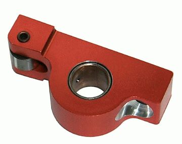
Roller Rockers - weight 110 grams (with
adjusting screw & nut)
The advantage of this type of rocker arm is
that it incorporates a roller design end tip which allows the roller to roll
across the valve stem during valve opening and closing sequences, thereby
greatly reducing valve stem side thrust loads. The rocker arm design
incorporates an oilite bushing rather than a needle roller bearing assembly.
Although this needle roller bearing produces less friction, the oilite bushing
has a lower wear rate, and especially when combined with a nitrided or
tuftrided rocker shaft; we are looking at a longer life for this
component.
One of the disadvantages of roller rocker arms is that they have a much high moment of inertia than the stock OEM rocker arm; this is because of the heavy roller that is far from the pivot axis. Since most of the weight of the rocker arm is farther away from the pivot axis than the OEM rocker arm, the valve spring sees more of the roller rocker arm's weight; this means that increased spring pressures are required to go to the same maximum engine RPM as compared to the stock OEM rocker arm.
RECOMMENDATIONS
Rocker Ratios (IRAR's)
Choose a
ratio in conjunction with camshaft lift that is compatible with your cyl/head
CFM flow rate. There is no need to open the valves further if CFM changes are
not significant beyond that particular valve lift. Build your valve timing and
duration requirements into camshaft design and build your valve lift CFM flow
rate into IRAR's
Pushrods
Use 5/16" chrome moly or
tempered chrome moly tubular pushrods only. OEM solid type pushrods are
subjected to greater dynamic deflection at increased valve spring #'s and high
engine RPM's. See technical article MGB26.
Valve Springs
Valve spring #'s
should be kept to a minimum and be compatible with the appropriate camshaft
profile and intended maximum operating engine RPM range. Valve spring installed
heights should be equal to maintain identical valve spring seat #'s. Be careful
to avoid valve spring coil bind conditions due to excessive valve lifts.
Valves
Valve installed heights
should be the same for all exhaust valves, likewise, for all intake valves.
However, exhaust to intake valve installed heights will probably be different.
Installed valve heights dictate the rocker arm horizontal plane position (valve
closed), and pushrod alignment angle.
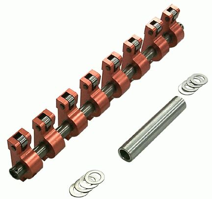
ROCKER ARM ASSEMBLY INSTALLATION
If you look closely at the MGA/MGB OEM complete rocker arm assembly,as
fitted to the engine, you will notice that several of the rocker arms do not
line up centrally over their respective valve stem center lines.
If you are installing the British Automotive supplied roller rocker kit, you can improve this situation as follows:
Machine your existing rocker shaft support pedestals (4) by removing .025" from both sides of each pedestal.
Assemble the rocker shaft and roller rockers in the normal manner then, without the pushrods installed, install the assembly to the cylinder head.
Torque cylinder head nuts to 25ft/lbs and the rocker pedestal nuts to 15ft/lbs.
Centralize the rocker arms over their respective valve stems and calculate how many .025" shims will be required to accomplish this. Not all of the rocker arms will need shimming. No other shim sizes are provided, so, get the rocker arms as central as possible.
* Number your rocker arms and rocker pedestals. Remove the assembly from the cylinder head, dismantle and install the shims that you calculated above.
Install the pushrods and rocker assembly in the normal manner. Torque cylinder head and rocker pedestal nuts per your workshop manual.
* To reduce friction and potential rocker arm "wander" over the valve stem, we also recommend the following:
When installing the .025" shims, leave out the 3 wire springs. Install the assembly as outlined earlier. (pushrods still removed).
Using a caliper dial gauge, measure the distance (3) between the rocker arms (these spaces were previously occupied by the wire springs). Subtract .020" from each of these measurements and record.
Machine the supplied aluminum bar to these recorded measurements.
Remove and dismantle the assembly and install these 3 spacers. Make sure that the outer spacers are in their correct location and that the rocker arms, and rocker pedestals, are fitted in the correct sequence.
Install the pushrods and rocker assembly in the normal manner. Check all pushrods for interference within their guide bores and also the vertical angle of the number 1 pushrod (when viewed from the side). Shims may have to be moved from the inside of the rocker arm to the outside Torque cylinder head and rocker pedestal nuts per your workshop manual. As you torque down, be sure that the 3 spacer tubes are free to rotate. Tap the pedestals to prevent this as you tighten
We supply 16 .025" spacer shims as part of the roller rocker kit, which should be more than sufficient.
If you are using 5/16" chrome moly tubing pushrods be aware that pushrod interference is more of a problem. In the engine rebuilding process we enlarge the guide tube holes to .660".