|
|
BRITISH AUTOMOTIVE |
|
www.mgbmga.com MGTD Articles |
Technical Information (MGB 32)
COOLING SYSTEM MODIFICATION
Last Updated 07/29/06
One of the best investments that you can make on improving the integrity of your MGB 63-76 cooling system is the installation of a coolant recovery system. The modification we will be discussing is the installation of a pressurized expansion tank system similar to what is found on the 1977 and later MGB's.
It is ironic that it took the factory so long to consider this type of cooling system improvement because the MG1100 (circa early 1960s) came with this system as standard.
Moving on... If you consider the 3 ways of improving your engine output; i.e., volumetric efficiency, mechanical efficiency and thermal efficiency. Of the three, improving thermal efficiency is the most often overlooked. Many MGB owners are proud of the fact that their vehicles are running so cool, especially in the height of summer. However, running your engine at low coolant temperatures will rob the engine of potential power output.
The MGB cooling system capacity did not change that much over the years (1963-1976 6 US quarts, and 1977 onwards 7 US quarts). I believe these capacities to be more than adequate when other related components are functioning correctly.
Consequently, it is my recommendation that 1963-76 models be updated to include a pressurized cooling expansion tank system as found on the 1977 and later MGB’s.
The main benefit of utilizing such a system is that the cooling system is now integrally sealed from the outer environment. With the knowledge that there are no internal or external coolant leaks present, the MGB owner can be assured that the coolant level will remain constant. However, there are occasions under extremely high ambient temperatures when the expansion tank will not be able to handle the coolant expansion, and in fact may overflow. Fortunately, this is not a very common problem. If this should occur, we see no problem in fitting some sort of plastic bottle, or container, to handle this additional overflow.
Looking back on the various years of MGB production models, we gain an insight as to how the cooling system changes were made by the factory.
| Years | Radiator Cap | OEM P/N |
|---|---|---|
| 1963-67 | 7 lbs. | GRC102 |
| 1968-75 | 10 lbs. | GRC109 |
| 1976 | 13 lbs. | GRC111 |
| 1977 and later | 15 lbs. | GRC110 |
Due to increasing exhaust emission requirements over these years, the factory was mainly required to run leaner fuel mixtures and retarded ignition timing, as well as API, Gulp Valve and Throttle Plate Poppet Valves. The leaner fuel mixtures, along with retarded ignition timing, brought about higher combustion chamber temperatures along with a more efficient combustion.
In 1972 yet another major change was made, the 18V low CR 8:1 engine was introduced to the USA market. Back on the “Merry Go Round”. Once again, there is a limit to reducing exhaust emissions by way of lean mixtures and running retarded ignition settings, peak combustions temperatures will eventually lead to high exhaust HC content. Reducing the CR is one way of achieving this.
Image P0003216 below shows the partial kit that British Automotive will supply you. These parts are as follows:
- Expansion Tank Mounting Bracket
- Radiator Blanking Cap
- Expansion Tank Support Bracket (with hardware)
- Insulation Rubber Strip
- Radiator Hose Nipple
PART # TANK/KIT
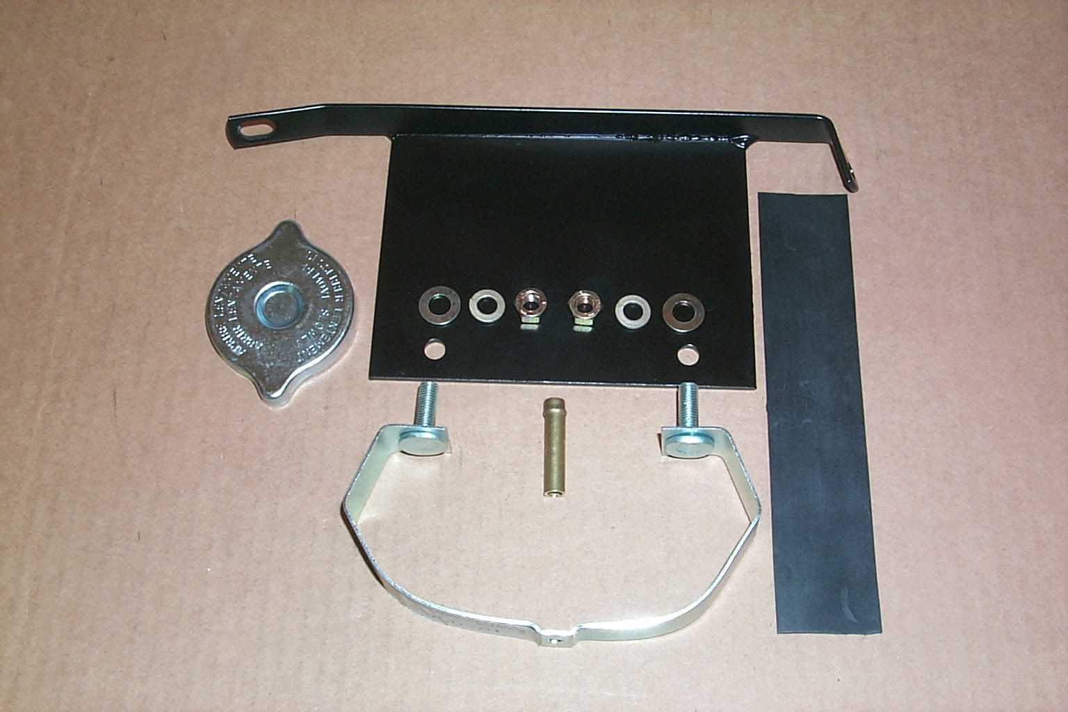
Image P0003217 below shows the additional components that you are required to locate and install to make the installation happen. These parts are as follows:
- 1977-80 MGB Expansion Tank
- 13 lbs. Lever Type Radiator cap
- 2 - #4 Micro Hose Clamps
- 2 ft. 5/16” Radiator Overflow Hose
- 2 ft. 5/16” High Pressure Hose
- 5/16” Hose Barb Fitting
NOTE: Unfortunately, at this time we are not equiped to locate and provide you with these additional parts.
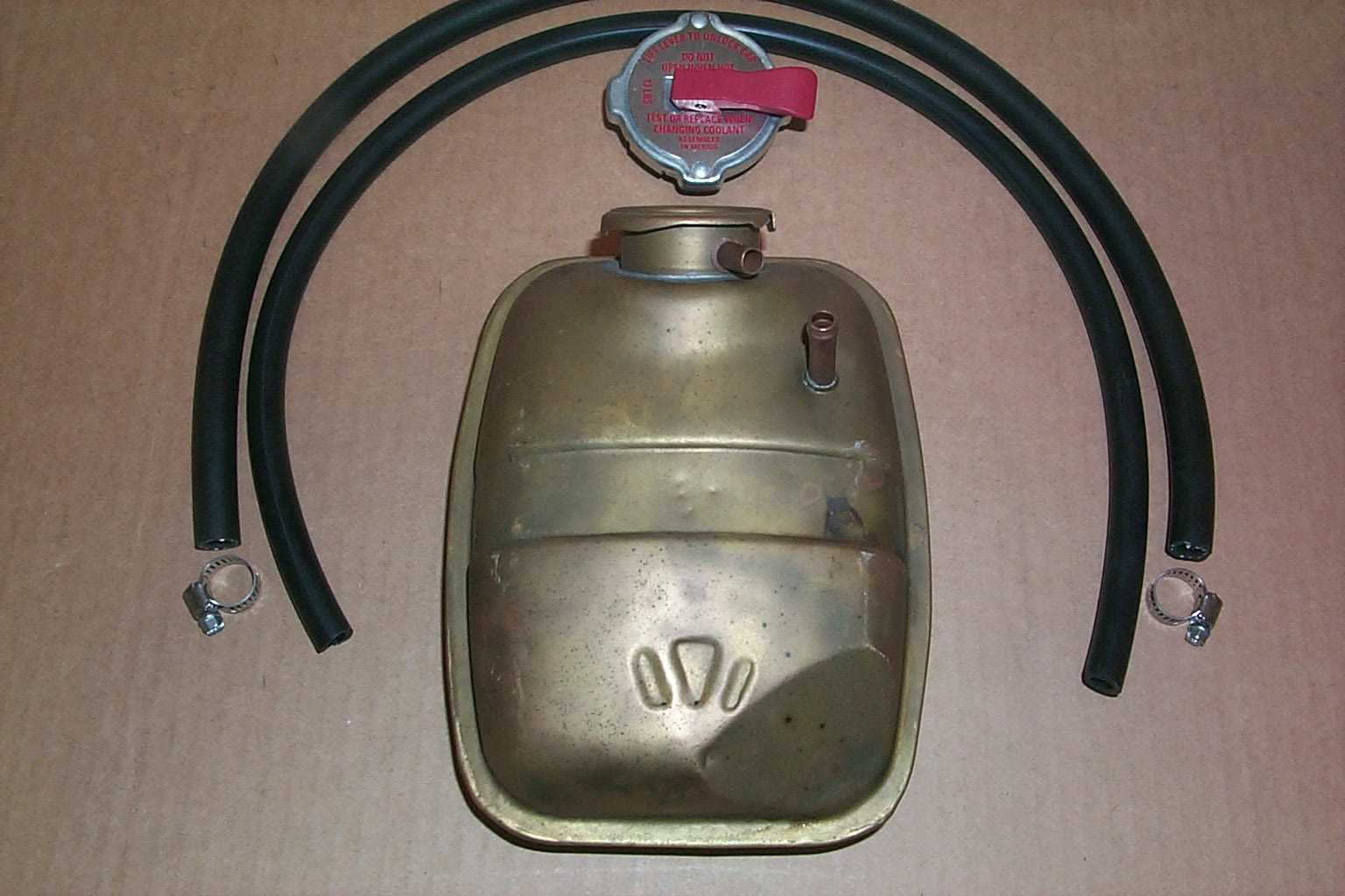
Image P0003214 below shows the entire components required for the successful installation of this kit.
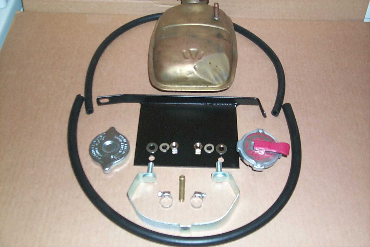
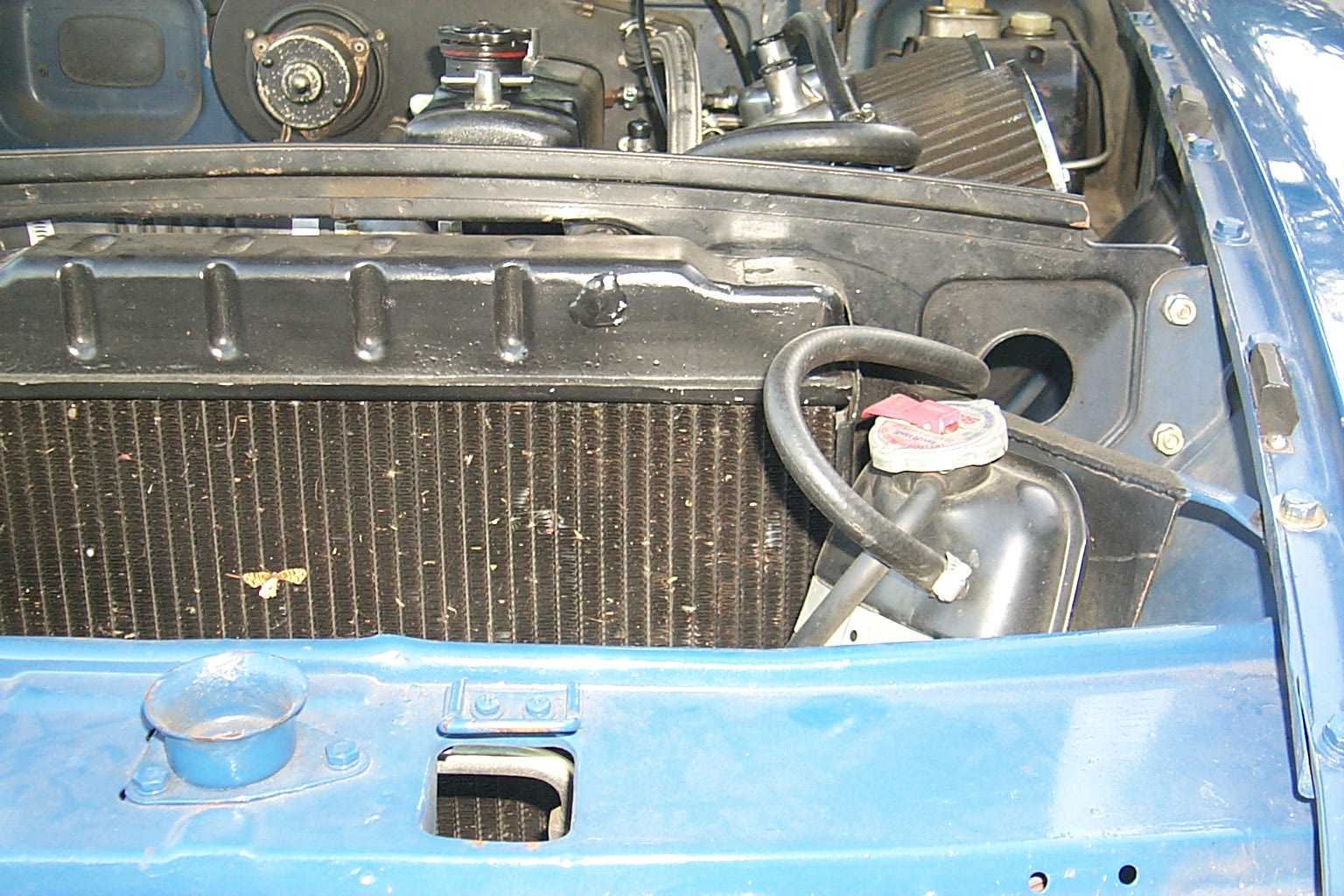
Image P0003165 below shows the complete kit as fitted to a 1967 MGB. NOTE: Installation of an electric fan kit will interfere with the fitting of this kit.
Prior to carrying out the following instructions, we advise having the complete cooling system, including the heater system, flushed. For environmental reasons, we recommend an approved facility for this operation.
- Drain radiator contents in to a suitable container, save for recycling or appropriate disposal.
- Remove upper and lower radiator hoses.
- Remove both L/H and R/H radiator support bars.
- 1963-67 models. Remove the six bolts securing the radiator to the radiator support frame along with the 8 bolts securing the radiator support frame to the body.
- 1968-76 models. Remove the six bolts securing the radiator to the radiator support frame.
- Remove radiator
- Remove L/H horn assembly (pre 1974.5 models only).
NOTE: While the radiator is removed from the vehicle, we recommend having the radiator clean out and repaired if necessary. Have the radiator shop replace the conventional radiator filler neck overflow tube with the 5/16” hose barb fitting. This fitting will require cutting to length. Also, we recommend having the original OEM drain tap replaced with American wing nut version. If your radiator does not have a drain tap fitted, consider having one fitted, you will be more than pleased you did when next drain your cooling system.
Before continuing with the installation, consider the following recommendations:
A. Consider having your water temperature, oil pressure combination gauge rebuilt (63-67).
B. Remove heater hoses and reverse flush the heater core until clear. This can be done by simply attaching a garden hose to the upper heater outlet fitting. Fit new heater hoses if necessary.
C. Replace heater control valve. If you old valve is functional, keep it as a spare.
D. Install new 82-degree thermostat.
E. If there is any doubts about the water pump, replace it.
F. Replace temperature-sending unit (1968 on) with the later unit (1977 on). In the past, we have found installing the earlier sending units give higher than normal gauge readings.
Installation Instructions continued...
- Re-install radiator and radiator support frame.
- Install new radiator hoses as necessary.
- Install R/H radiator support bar.
- Fit expansion tank to the expansion tank support bracket and install assembly.
NOTE: The L/H radiator support is incorporated with the expansion tank support bracket.
- Fit the 5/16” high-pressure hose to the lower expansion tank barb fitting. Secure with hose clamps.
- Install 5/16” overflow hose to expansion tank upper fitting. Direct hose downwards and alongside the radiator.
- Fill expansion tank half full of anti-freeze. Top off with regular water. Install pressure radiator cap.
- Fill radiator with 50/50 concentration of anti-freeze and water. Spray underside of radiator blanking cap with WD40 and install.
- Place the horn assembly, if removed, into position. If the original mounting holes do not line up due to the horn contacting the base of the expansion tank, simply lower the horn assembly and drill two additional 17/64” mounting holes.
- Start engine and check for coolant leaks. When engine has cooled down, retighten all hose clamps.
- Slowly release expansion tank pressure cap and make sure tank is at least half full.
- Remove radiator blanking cap and top up radiator with 50/50 concentrate.
NOTE: For your reference, always use this method of checking coolant levels.