|
|
BRITISH AUTOMOTIVE |
|
www.mgbmga.com MGTD Articles |
Technical Information (MGB 3)
MGB/MGA SIDE PLATE COVER OIL LEAKS
Last modified 09/08/05
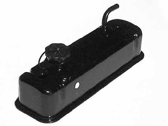
British Automotive now has in stock the latest production of the aluminum non-vented style one-piece side plate cover assembly. These new production covers are identical to their predecessors except that the material thickness has been reduced from 3/4” to 1/2” as well as being black anodized instead of gold color. Reduced weight is now 2.0 lbs.
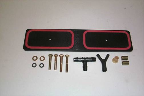
The appropriate components for your application will be found within the following parts list:
| Qty | Description | Text ID |
|---|---|---|
| 1 | Non_vented Cover Assembly | A |
| 2 | Rubber Gaskets | B |
| 2 | 5/16" SAE X 1-3/4" Bolt (MGA & MGB 3 Main Bearing) | C |
| 2 | 5/16" SAE X 1-3/4" Bolt (MGA & MGB 3 Main Bearing) | D |
| 2 | 5/16" SAE Flat Washers | E |
| 2 | 5/16" Fiber Washer | F |
| 1 | 1/2" "T" Piece | G |
| 1 | Zenith Stromberg Adapter | H |
| 2 | 1/2" PCV Hose Restrictor | I |
| 1 | "Y" Piece Adapter | J |
The advantages of this one-piece side plate cover design are as follows:
- Allows positive location of the rubber gaskets within the cover assembly,
- Centralization and alignment of the cover is assured due to one-piece construction, and
- Positive tightening of the cover assembly without the dreaded “squeeze out” effect.
Oil transfer from the OEM style side plate cover was very noticeable on the 65 through early 68 engines with the OEM installed PCV valve. Upon inspection you will notice that there always appears to be a pool of oil inside the valve assembly. The later, 68 and onwards, carburetor control type system was not as prone to oil transfer as this earlier system
With the introduction of the PCV system came a new style of front side plate cover 18GB to 18V. With still a later style cover being introduced on the 18V engines. This later style is preferable due to its better breathing and the oil reservoir/return chamber incorporated in the cover design.
Excessive crankcase "blow-by" conditions will considerably increase oil transfer problems regardless of what type of system is used. Good piston ring sealing is very important and the number one factor in controlling oil consumption and related oil transfer problems into the combustion chamber such as "pinging".
Also, be advised that with the installation of Total Seal piston rings (potentially increased engine vacuum), intake valve guides wear problems must be taken care of. This increased engine vacuum could also increase oil transfer into the combustion chamber via the PCV system.
Over the many years I have concluded, in regards to the MGB PCV controlled engine that is, that the side plate cover area is not the most ideal area to ventilate crankcase gases from. Apart from racing applications, I see no reason why the crankcase breathing can not be directed from the valve cover.
The one-piece side plate cover’s major job now is in eliminating reoccurring oil leaks, which the OEM style side plate covers were prone to.
With the installation of this cover, crankcase breathing can now be directed from the valve cover to your applicable OEM hook-up.
MGA & MGB 63-64 Front air cleaner.
MGB 65-68 (early) OEM PCV valve.
MGB 68 (late) – 74.5 HS4 or HIF4 carbs.
MGB 75-> Zenith/Stromberg carburetor
There was no OEM PCV system fitted to these models. A simple road draft tube was incorporated at the front side plate cover along with a breather hose from the valve cover to the front air cleaner assembly. The MGA front air cleaner design allowed unrestricted "blow-by" gas flow. To prevent unrestricted "blow-by" gases the MGB front air cleaner had a 5/32" restricter orifice incorporated in its design. In both cases, the crankcase breathing system was balanced with a metal vented oil filler cap incorporating a 1/8" bleed orifice.
You can install the one-piece side plate cover and still use the original valve cover and breather hose layout. The obvious problem with this set up was that all of the crankcase "blow-by" gases were directed into the front air cleaner resulting in a contaminated mixture charge. To better balance the crankcase "blow-by" gases you could install another front air cleaner to the rear carburetor, or purchase and install, a 1/2" OD adapter breather fitting to your existing rear air cleaner.
Use 1/2" "T"-Piece to connect the two air cleaners together. Hook up the original valve cover breather hose to the 1/2" "T"-Piece. Drill out the 1/16” pilot hole in each restricter to 5/32" and install inside 1/2" PVC hose at each air cleaner. Retain original steel vented oil cap, or update to the later plastic style vented oil cap incorporating a 5/32" bleed orifice.
When using the prescribed above method, the following components will be required:
1 of A
2 of B
2 of C
2 of E
2 of F
1 of G
2 of I
NOTE: Neither the ˝” OD breather hose adaptor,or the 1/2” PCV hose, are supplied by British Automotive.
You can use the same method as with the MGA. However, this would require the fitting of a front air cleaner backing plate, or a 1/2" OD breather adapter fitting. Hook up as in the MGA section above. If you are using the 1/2" adapter fitting method you will need to install a 1/2" hose restricter, drilled to 5/32”, in the 1/2" PCV hose at the rear air cleaner.
When using the prescribed method, as mentioned in the MGA information, the following components will be required:
1 of A
2 of B
2 of C
2 of E
1 of G
1 of I
NOTE: Neither the ˝” OD breather hose adaptor, or the ˝” PCV hose, are supplied by British Automotive.
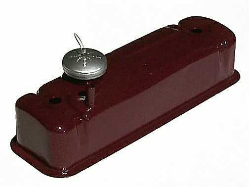
The OEM PCV valve system was fitted to these particular year models. The valve cover had no provision for a vent elbow. A plastic vented oil cap was introduced with a 5/32” bleed hole.
Since this style of valve cover as no vent elbow, you may want to install a suitable adapter such as K&N part number 85-1120. This will require that you install the 1/2” restricter (drilled to 5/32”)inside your original crankcase breather hose which, leads to the OEM PCV valve. You could also install a later valve cover assembly found on 1970 models and onwards. This will require that you enlarge the vent elbow bleed orifice from the original 5/64” to 5/32”. Retain OEM plastic vented oil cap.
When using the above-prescribed method, the following components will be required:
1 of A
2 of B
2 of D
2 of E
2 of F
1 of I (If K&N 85-1120 fitted)
NOTE: K&N 85-1120 and 1/2” PCV hose are not supplied by British Automotive.
These particular year models had an updated PCV system which, directed crankcase "blow-by" gases, via a "Y" connector, to both front and rear HS4 carburetors.
The same installations instructions apply as in the previous paragraph, with the crankcase breather hose now being directed to the OEM “Y” piece.
When using the above prescribed method, use the components outlined in previous paragraph with the additional component.
1 of J
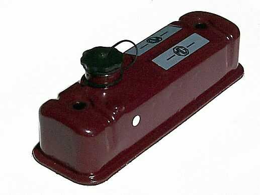
This valve cover had a plastic non-vented oil filler cap. A vent elbow was also incorporated in the design. This vent elbow had a 5/64” bleed orifice, and was directed at right angles to the valve cover. The color maroon was found on 1970-71 models and black thereafter.
These particular year models had the same PCV system as mentioned in the previous section. The exception being the introduction of a charcoal cannister with balanced crankcase breathing now being directed through the carcoal cannister.
Install 1/2" "T"-piece into the charcoal canister line. Fit 1/2” PCV hose between vent elbow and “T” piece. Direct the 1/2" PCV hose to the original "Y" connector, with the 1/2" hose restrictor (5/32" ID) abutting the "Y" connector. Install plastic vented oil filler cap.
When using the above prescribed method, the following components will be required.
1 of A
2 of B
2 of D
2 of E
1 of G
1 of I
1 of J
NOTE: 1/2” PCV hose is not supplied by British Automotive. Order vented oil filler cap (460-105) separately.
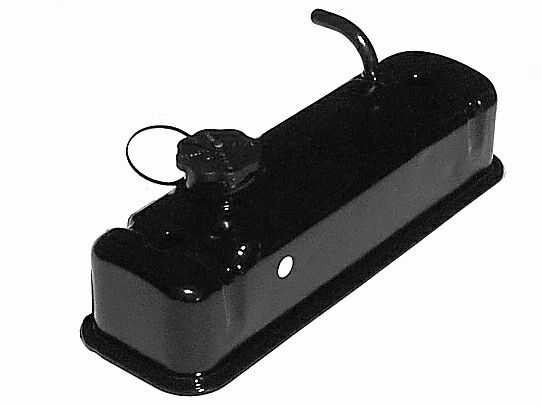
The only difference with this valve cover design is the vent elbow that was directed at right angles to the valve cover in the 70-74 models was now directed rearwards.
These particular models used a similar PCV system as mentioned previously.
Install 1/2" “T” piece in charcoal cannister line.Fit ˝” PCV hose between “T” piece and vent elbow. Install Zenith Stromberg adapter on carburetor male port. Install 1/2” PCV hose between “T” piece and the aforementioned adapter with the 1/2” restrictor (5/64”) inserted in the hose nearest the carburetor. It is extremely important that this restrictor is installed. Carburetor idling and running problems will be evident if this is not done.
When using the above prescribed method, the following components will be required:
1 of A
2 of B
2 of D
2 of E
2 of F
1 of G
1 of H
1 of I
NOTE: 1/2” PCV hose is not supplied by British Automotive. Order vented oil filler cap (460-105) separately.
- MGA FRONT AIR CLEANER HOSE FITTING WAS UNRESTRICTED
- MGB FRONT AIR CLEANER HOSE FITTING HAD 5/32” BLEED HOLE
- STEEL VENTED OIL CAP HAD 1/8” BLEED HOLE
- PLASTIC VENTED OIL FILLER CAP HAD 5/32” BLEED HOLE
- VALVE COVER VENT ELBOW HAD 5/64” BLEED HOLE
The 1/2” PCV hose restrictor is supplied with a 1/16” ID hole.From the above, we have basically applied this information to the various crankcase breathing systems in recommending the actual ID size of the restrictor.
Obviously, the larger the hole ID, the greater a chance of oil transfer to the induction system. Obviously, this depends upon the condition of your engine.
First, we recommend installing the PCV hose restrictor with the original 1/16” ID hole. Monitor for excessive “blow-by” crankcase pressure before deciding to proceed with any enlarging of this hole diameter. These conditions may be manifested by oil being blown out of locations such as the oil dipstick tube, oil filler cap and even the charcoal cannister.
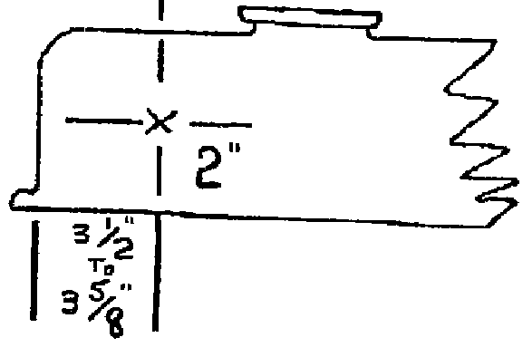
Drill and file the K&N adapter hole to the appropriate size in the location shown. Install the adapter. To prevent oil seepage, be sure to use an appropriate sealer.
Follow the procedure for OEM side plate removal and refitting as outlined in the appropriate workshop manual along with the following:
Install and properly seat the rubber gaskets, without gasket sealer, into their channels. Apply a small amount of gasket sealer to each gasket face and to one side of the fiber washers. Install side plate cover and secure with 5/16” SAE bolts, making sure that the fiber washers are between the flat washer and the cover. Evenly tighten bolts to 6lb/ft. DO NOT EXCEED.
NOTE: Improved crankcase breathing balance is achieved by installing the vented type oil filler cap on engines that were originally fitted with the non-vented type. Subsequently, carburetor(s) will have a tendancy to run slightly leaner with the above installation. Re-adjust mixture if necessary.
For the correct emission control layout for your particular MGB model see the MGB Moss Motors Parts Catalog under "Emission Controls".