|
|
BRITISH AUTOMOTIVE |
|
www.mgbmga.com MGTD Articles |
Technical Information (MGB 27)
TRACTION CONTROL ARM KIT (ALL MGB &
MGBGT)
Updated 01/28/03
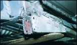
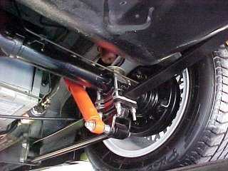
LEFT REAR VIEW
Although specified as a "Traction Control Arm Kit" We have found
this product to be ideal as a "Rear Axle Locating Device". Positively
locating the rear axle under all rear suspension operating conditions.
Specifically designed for MGB roadsters and the MGBGT that have been
fitted with COMPOSITE SPRINGS.
This kit will work with banjo axles, tube
axles and Ford 8" rear ends using the MGB tube axle type "U"-bolt bolt
pattern.. The designated part numbers are as follows:
| TCAK/CBBA | All chrome bumper MGBs fitted with banjo axles. |
| TCAK/CBTA | All chrome bumper MGBs fitted with tube axles. |
| TCAK/RBTA | All rubber bumper MGBs fitted with tube axles. |
| TCAK/RBBA | All rubber bumper MGBs that may be fitted with banjo axles. |
This kit allows maximum power to be applied, usually from standstill, without the noted axle "hop" occurring.
Complete bolt-in installation for MGB's fitted with OEM or telescopic shock absorbers and COMPOSITE SPRINGS ONLY.
OEM Steel spring design dictates the need for a deeper lower shock absorber mounting bracket. Unfortunately, this presents ground clearance problems, therefore, we have decided not to fabricate this item due to this problem.
The above illustration shows the installed assembly in conjunction with British Automotive's telescopic shock absorbers. Before converting to telescopic shock absorbers, be sure to read technical article MGB13 " Telescopic Shock Absorbers".
DESIGN CRITERIA
The criteria for a "traction control device", also called "anti-tramp bar" installation
for street
applications differ from race or drag strip applications.
The primary problem
that any design will run in to is ground clearance problems.
This ground
clearance problem has very little effect on vehicles used
solely for racing or
solely for drag strip purposes. However, for street purposes
it becomes a very
big issue.
We have looked at various products and designs on the market
and found this to be the number one issue.
Another issue that is put out
there is the statement "this kind of traction control device increases the
spring rate and will "bind-up" therefore, contributing to rear wheel
steer".
We acknowledge that this device will have a tendency to increase the spring
rate, however, this increase is relative to how flat the installed road
spring is on the vehicle and the amount of rear suspension movement.
In regards to "bind-up" issues, after installing the traction
control arm kit, we carried out a test with surprising results. See further
information within text.
British Automotive's design takes these 2 issues into account.
We have designed a product that allows:
1. The maximum ground clearance
relative to the composite spring installation.
2. The "traction control
arm" to scribe virtually the same arc as that of the rear axle during
suspension movement.
Further, this "traction control device" was designed around
British Automotive's 1979 MGB "Limited Edition", which has a rear ride
height
of 15" (measured from the center of the road wheel to the underside of
the
chrome strip) fitted with Composite Springs.
With this 15" rear ride height in mind, we designed the
front and rear control arm mounting brackets to give adequate
ground
clearances. We would have liked the control arm to be horizontal,
however, we
reached a compromise which, resulted in the installation
being at a slight
angle.
Our next venture was to install the complete "traction control
kit" to the vehicle and check for "binding problems" under full axle "bump" and
"rebound" conditions.
As luck would have it, I procured the services of
two individuals with a combined weight of approximately
550 lbs. Both people
sat directly on top of the left rear fender. This amount
of weight probably
more than duplicated "bump" conditions because the bump stop was compressed
considerably.
If the "traction control arm" were actually causing
"binding problems" then we would have a hard time removing either one of
the
bar mounting locating bolts. In turn, I was able to remove
these bolts by hand
and reinsert each bolt with a slight tap of a hammer with
very little
resistance.
Under full "rebound" conditions, with the longer axle check
straps in place and the exhaust muffler/tailpipe removed,
we were able to
remove and reinsert both bolts very easily.
With this exaggerated test, one surely could conclude that
under normal rear suspension movement, the traction control arm is not
a contributing factor in any abnormalities that may be occurring in the
way the vehicle is handling.
These instructions should be read in conjunction
with the appropriate section of the MGB workshop manual i.e. rear road spring
replacement.
NOTE: FOR EASIER INITIAL INSTALLATION USE FLAT
WASHERS ONLY. INSTALL THE PROVIDED LOCKWASHERS UPON FINAL ASSEMBLY. ALSO, ALL
JAGGED EDGES, CAUSED BY DRILLING, MUST BE FILED FLUSH.
WORK ON ONE SIDE AT A
TIME. START ON THE RIGHT SIDE FIRST. LEFT HAND SIDE REQUIRES THE PARTIAL
REMOVAL OF THE REAR EXHAUST SYSTEM.
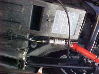
The above image shows the right hand side bracket installed. The front traction control arm mounting bolt is installed in the lower hole.
NOTE: MGB OWNERS THAT HAVE V6 OR V8 POWER UNITS, OR EVEN HIGHLY MODIFIED OEM ENGINES, MAY HAVE CONCERNS ABOUT THE STRENTHENING OF THE AREA IMMEDIATELY FORE OF THE SPRING EYE MOUNT.
TO THIS END BRITISH AUTOMOTIVE IS DEVELOPING A FLOOR STRENGTHENER KIT. DETAILS AND AVAILABILITY OF THIS KIT WILL BE POSTED ON THE WEBSITE AS SOON AS THIS PRODUCT IS READY FOR MARKETING.
BRITISH AUTOMOTIVE'S PRODUCT WILL BE "BOLT-IN" UNLIKE THE
PRODUCT SHOWN BELOW.
MGOC
mgbv8 prototype.jpg RV8 rear axle 2.jpg RV8 rear axle.jpg
The above images courtesy of MGOC UK.
The following instructions pertain to installing the
traction control arm kit to the existing Composite Springs. If you
are installing Composite Springs at the same time, complete the Composite
Spring installation first.
Using your MGB workshop manual as a guide continue as follows:
Support vehicle with jack stands under rear axle tubing.
Remove axle check straps.
Remove OEM shock absorber link or telescopic shock absorber lower mounting hardware.
Support vehicle with jack stands supporting body.
Remove lower shock absorber mounting bracket. See note below.
NOTE: If you have British Automotive's earlier designed lower shock absorber mounting bracket (tube axles only); you will have to update to the later bracket found in traction control arm kit. For identification purposes, the earlier brackets had no provisions for mounting the traction arm.
Support rear axle tubing with hydraulic jack.
Remove forward spring eye mounting hardware.
Position inner and outer traction control arm support brackets. Insert longer front spring mounting bolt and finger tighten nut.
To help in this bracket location, insert traction control arm heim joint bolt. It is extremely important that the centers of both upper and lower holes are vertically aligned. Use a small "level" for this purpose.
Mark location of the upper floor panel attachment holes (3) on the underside of the floorpan.
Remove support brackets, accurately drill 1/8" pilot holes.
NOTE: Be sure to pull back carpets to avoid damage from drill bit.
From inside the vehicle locate the 3 1/8" pilot holes. Remove sound deadening material as necessary. Drill the outer hole to 17/64" and the inner two holes to 21/64". Deburr holes as required.
Install support brackets with supplied hardware, do not overtighten hardware. Use supplied 1/4" and 5/16" SAE flat washers for spacing purposes if underside of floor pan is uneven.
Position spring, insert new mounting hardware bolt, finger tighten nut. If you are satisfied that the mounting holes for the traction control arm bolt line up, vertically and horizontally, then you can tighten traction control arm support bracket hardware. After tightening hardware, recheck for insertion of traction control arm bolt.
If required, install modified lower shock absorber mounting bracket.
Lubricate traction control arm polyurethane bushing faces. Install traction control arm to the lower shock absorber mounting bracket. Do not tighten hardware at this stage.
Support traction control arm with mechanics wire or suitable material. Do not install front heim joint hardware at this time.
Repeat the above instructions for the opposite side.
Once you have completed installation on the opposite side continue with the following:
Support vehicle with jack stands under rear axle tubing.
Install rear axle check straps.
Install OEM shock absorber links or telescopic shock absorber lower mounting hardware.
Lower vehicle to the ground, roll vehicle backwards and forwards to settle suspension.
With the vehicle on the ground, ramps or vehicle lift, adjust each heim joint to accommodate hardware. Tighten rear suspension hardware including heim joint jam nuts.
INSTALLATION INSTRUCTIONS (RUBBER BUMPER MODELS)
These instructions should be read in conjunction with the appropriate section of the MGB workshop manual i.e. rear road spring replacement.
NOTE: FOR EASIER INITIAL INSTALLATION USE FLAT WASHERS ONLY. INSTALL THE PROVIDED LOCKWASHERS UPON FINAL ASSEMBLY. ALSO, ALL JAGGED EDGES, CAUSED BY DRILLING, MUST BE FILED FLUSH. WORK ON ONE SIDE AT A TIME. START ON THE RIGHT SIDE FIRST.LEFT HAND SIDE REQUIRES PARTIAL REMOVAL OF THE REAR SECTION OF THE EXHAUST SYSTEM.
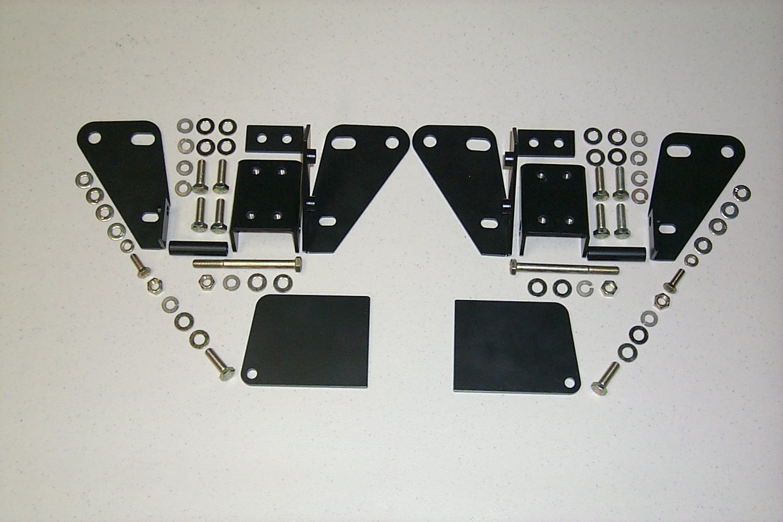
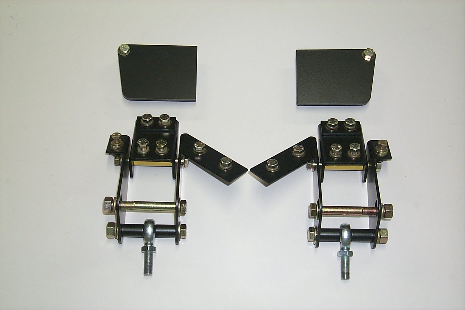
P0002428 P0002495
The above left-hand image shows the unassembled bracket
kit. The above right-hand image shows the bracket kit assembled with
traction control arm heim joint in position.
These instructions pertain to installing the traction
control arm kit to the existing COMPOSITE SPRINGS.
If you are installing Composite Springs at the same
time, complete the Composite Springs installation first.
Using your MGB workshop manual as a guide continue as follows:
Support vehicle with jack stands under rear axle tubing.
Remove axle check straps.
Remove OEM shock absorber link or telescopic shock absorber lower mounting hardware.
Support vehicle with jack stands supporting body.
If necessary, remove lower shock absorber mounting bracket. See note below.
NOTE: If you have British Automotive's earlier designed lower shock absorber mounting bracket (tube axles only), you will have to update to the later bracket found in the traction control arm kit. For identification purposes, the earlier brackets had no provisions for mounting the traction arm.
Support axle tub with hydraulic jack.
Remove forward spring eye mounting hardware.
Mgb27_ill_3.gif Mgb27_ill_4.gif
The left-hand image above shows the floor strengthener plate kit. The right-hand image shows the traction control arm support brackets.
NOTE: MGB OWNERS THAT HAVE V6 OR V8 POWER UNITS, OR EVEN HIGHLY MODIFIED OEM ENGINES, MAY HAVE CONCERNS THAT THE FLOOR STRENGTHENER PLATE KIT ABOVE MAY BE INADEQUATE.
TO THIS END BRITISH AUTOMOTIVE IS DEVELOPING A FURTHER FLOOR STRENGTHENER KIT. DETAILS AND AVAILABILITY OF THIS KIT WILL BE POSTED ON THE WEBSITE AS SOON AS THIS PRODUCT IS READY FOR MARKETING.
Instructions continue...
Position inner and outer brackets (D). Insert longer front spring mounting bolt, and finger tighten nut.
For location purposes, insert traction control arm heim joint bolt. It is extremely important that the centers of both upper and lower holes are vertically and horizontally aligned. Use a small "level" for this purpose.
Mark location of the upper floor panel attachment holes (3).
Remove support brackets (D).
From inside the car, slide seat forward as far as it will go. Pull back carpet.
From underneath, accurately drill marked locations with 1/8" pilot holes.
From inside the car, place upper floor strengthener plate (A) into corner position, then scribe the plate outline. Remove any deadening material from within this scribed area, as well as, the 1/8" pilot holes.
From inside the vehicle drill the outer hole to 17/64" and the inner two holes to 21/64". Deburr holes.
Position the upper floor strengthener plate (A), then mark and drill the forward 21/64" hole through floor panel. Insert 5/16" bolt, finger tighten nut.
From underneath the vehicle mark the 17/64" hole through the floor panel on to the strengthener plate (A). Remove plate and drill to this size.
Reposition strengthener plate (A). Insert 5/16" bolt, finger tighten nut.
Reposition traction control arm support brackets (D). Secure (loosely) with provided 5/16" bolts, along with 1/4" bolt passed through strengthener plate (A).
Align upper spring and lower traction control arm mounting holes. Fit spring eye mounting hardware. Do not overtighten.
Use supplied 5/16" and 1/4" SAE flat washers for spacing purposes if underside of floor pan is uneven.
Gradually, conservatively tighten all hardware, taking into consideration that the traction control arm mounting holes must be aligned both vertically and horizontally. Keep checking by inserting the mounting bolt for fitment.
Scribe inner support bracket (A) vertical elongated hole on to the road spring support abutment.
NOTE: The next instruction must be carried out as accurately as possible. Use the smallest chuck sized pistol drill or right angle drill available.
Using the center of the scribed elongated hole as a reference, drill 1/8” pilot hole through the inner road spring support only. Change drill bit to 21/64”. Drill out the 1/8” pilot hole, on and through the outer road spring support. Keep the drill bit as straight as possible. Deburr holes.
Place "U" bracket (B) into position, along with spacer (C), secure with provided 5/16" SAE X 3/4" bolts and nuts.
Mark location of "U" bracket (B) securing bolts (4) on to the underside of floor pan. Remove "U" bracket (B).
Drill 1/8" pilot holes (4) through floor pan into, but not through, the upper strengthener plate (A).
Remove strengthener plate (A) and drill 1/8" mark holes to 21/64". Likewise, drill out floor pan pilot holes to same size. Deburr drilled holes.
Install "U" bracket (B), substituting the 5/16" SAE X 3/4" bolts with the 5/16" SAE X 3.5" SAE bolt.
If required, install modified lower shock absorber mounting bracket.
Lube faces of traction control arm polyurethane bushes, install arm
to
lower shock absorber bracket.
Support traction control arm with mechanics wire or suitable material. Do not
install front heim joint hardware at this time.
Conservatively tighten all hardware, finally tightening should be done with vehicle on the ground or level surface.
Repeat the above instructions for the opposite side.
Once you have completed installation on the opposite side, continue with the following:
Support vehicle with jack stands under rear axle tubing.
Install OEM shock absorber link or telescopic shock absorber lower mounting hardware.
Lower vehicle to the ground, roll vehicle backwards and forwards to settle the suspension.
With the vehicle on the ground, ramps or vehicle lift, adjust each heim joint to accommodate mounting hardware. Finally, tighten all rear suspension hardware including heim joint jam nuts.