|
|
BRITISH AUTOMOTIVE |
|
www.mgbmga.com MGTD Articles |
Technical Information (MGB 14C)
Steering
06/13/01
No modifications are required with the steering rack assembly, however, we would like to pass on to you several informative tips.The main bit of information is in regard to installing the steering rack assembly.
On the crossmember there are, or should be, metal shim tabs riveted on the mounting platform at the rear mounting holes. Normally there should be two per side with each shim tab being approximately .015" thick. Invariably we find these shim tabs to be missing. When you reinstall the steering rack assembly please take note of the following:
Offer the steering rack assembly into position and make note of the fore and aft tilt of the steering rack, also, check that the steering rack is not tilted horizontally. Use aircraft 5/16" AN washers of either.032" or .063"" to adjust the steering rack. There should be no tension on the steering rack tubing whatsoever.
Shims are available to adjust the damper assembly so as to remove steering rack vertical free play. If you are undertaking this job, now is the time to top up the steering rack assembly with 80W/90. Remember that the rack assembly correct capacity is only 1/3rd of a US pint.
If you are attempting to top-up the steering rack assembly, other than the above method, remove the drivers side small steering rack boot clamp, jack up the vehicle on the drivers side (be sure to support with jack stands). Fill a small oil pump can with the appropriate amount of 80W/90 oil. Using a small screwdriver, lift up the end of the boot and insert the nozzle of the oil can, pump in the oil. The tilted angle of the steering rack will allow the oil to run into the steering rack housing. Allow a little time for the oil to flow into the housing. Install the steering boot clamp, jack up the vehicle, remove jack stands, lower the vehicle down.
HARDWARE INFORMATION
Numerous OEM front suspension, rear suspension and steering bolts were of the shouldered type; these special shouldered bolts are substituted, within the parts order form, with regular grade 8 yellow zinc plated bolts along with lockwashers and regular nuts. Slotted nuts are clear plated.
Replacement bolts may, or may not, have the correct length of shoulder as the OEM type. Similarly specific bolts supplied from within the Moss Motors catalog may, or may not, duplicate the OEM bolts.
All plated bolt and nut threads must be lightly coated with oil before assembly. Do not overtighten.
OEM SHOULDERED BOLT INFORMATION
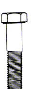
| THREAD | A | L1 | L2 | L3 | |
| BUMP STOP MOUNT (LONG) | 5/16" SAE | .308" | .565" | .935" | 1.500" |
| STEERING SHAFT U/JOINT | 5/16" SAE | .308" | 1.125" | .500" | 1.625" |
| STEERING RACK MOUNTING | 5/16" SAE | .308" | 1.125" | 1.000" | 2.125" |
| PIVOT ARM ATTACHMENT | 3/8" SAE | .372" | .500" | .750" | 1.125" |
| SHOCK ABSORBER MOUNTING | 3/8" SAE | .372" | .313" | .687" | 1.000" |
| BRAKE DISC TO HUB | 3/8" SAE | .372" | .375" | .750" | 1.125" |
| SWAY BAR LINK ATTACHMENT | 7/16" SAE | .434" | 1.000" | .750" | 1.750" |
| STEERING ARM ATTACHMENT | 7/16" SAE | .434" | 1.188" | .812" | 2.000" |
| BRAKE CALIPER MOUNTING | 7/16" SAE | .434" | .750" | .562" | 1.312" |
| REAR S/ABS. MOUNT | 7/16" SAE | .434" | 2.250" | 1.250" | 3.500" |
| LEAF SPRING FRONT MOUNT | 7/16" SAE | .434" | 2.250" | .687" | 2.937" |
| REAR AXLE CHECK STRAP | 5/15" SAE | .308" | .937" | .937" | 1.875" |
OEM REGULAR THREADED BOLT INFORMATION
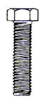
| THREAD | L3 | |
| SPRING PAN (INNER) | 5/16" SAE | 1.000" |
| SPRING PAN (OUTER) | 5/16" SAE | .875" |
| BRAKE DISC BACKPLATE | 5/16" SAE | .500" |
| SWAY BAR MOUNTING | 5/16" SAE | .625" |
| BUMP STOP MOUNT (SHORT) | 5/16" SAE | 750" |