|
|
BRITISH AUTOMOTIVE |
|
www.mgbmga.com MGTD Articles |
Technical Information (MGB 14AA)
Coil-Over Suspension Unit
Last Modified - 10/23/04
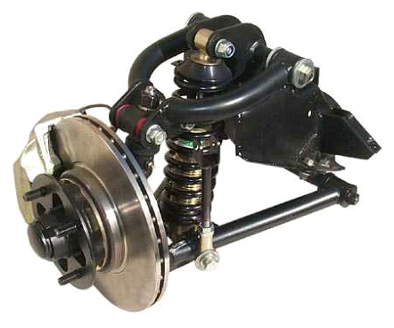
British Automotive introduces to the MGB owner Hawk Cars and Hoyle. A modern day design which can be considered when rebuilding your old front suspension unit. Cross-member modifications are required to install this unit, to this end British Automotive supplies, within the "Upgraded Kit", a template that the MGB owner to remove the necessary material from the cross-member without resorting to "cutting torch" techniques.
Suspension components that are retained are as follows:
1. Complete Front Swivel Assemblies. (2)
2. Lower Inner Wishbone Pivots. (2)
The standard coil-over suspension kit is shown immediately below. However, British Automotive has upgraded and expanded this kit to include additional components. In order to understand these additions and changes please refer to following images and accompanying text.
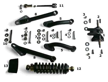
1. Top mount (2) 2. Top mount fixings (3/8" SAE X 1" Cap Screw) (8) 3. Upper Wishbone Fixings (1/2" SAE NYLOC Nut) (4) (5/8" ID X 1.250" OD Washer) (4) (1/2" ID X 1.250" OD Washer) (4) 4. Damper Fixings (Upper) (12mm X 65mm Bolt) (2) (12mm NYLOC Nut) (2) (12mm Washer) (4) 5. Upper Wishbone Assemblies (4) 6. Spacer Assembly (10mm X 80 mm Bolt) (2) (10mm NYLOC Nut) (2) (10mm Washer) (4) (Special Spacer) (2) 7. Upper Kingpin Fixings (1/2" SAE X 3.250" Bolt) (2) (1/2" SAE NYLOC Nut) (2) (1/2" Flat Washer) (4) (1/2" Caster Shim Washer) (8) |
8. Lower Wishbones (4) 9. Damper Fixings (Lower) (12mm X 100mm Bolt) (2) (12mm NYLOC NUT) (2) (12mm Flat Washer) (4) (Special Spacer) (4) 10. Lower Kingpin Fixings (1/2" SAE X 4" Special Bolt) (2) (1/2" SAE NYLOC nut) (2) (SPECIAL 'Snail CAM') (4) 11. Sway Bar Link (2) (1/2" SAE X 1.250" Bolt) (2) (1/2" Lockwasher) (2) (1/2" SAE Lock Nut) (2) (1/2" Rod End Bearing) (2) 12. Spring/Damper Unit (2) (#300) 13. Modified Crossmember Plate (2)
|
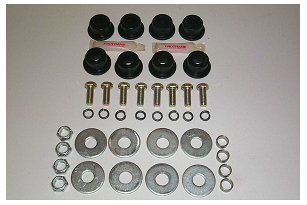
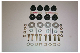
1 - POLYURETHANE MOUNTING PAD SET
4 - 1/2" SAE NYLOC NUTS
4 - 3/8" SAE X 1" GRADE 8 HEX HEAD BOLT
4 - 3/8" HI-COLLAR LOCKWASHER
4 - POLYURETHANE BUSHING
4 - PROTHANE LUBE
4 - 5/8" ID x 1.625" OD WASHER
4 - 1/2" ID x 1.625" OD WASHER
4 - SPACER TUBES (.300")
4 - 1/2" SAE NLNNTE NYLOC NUT
PLEASE NOTE: BOLTS THAT ARE PROVIDED ABOVE ARE THE NON SHOULDERED TYPE
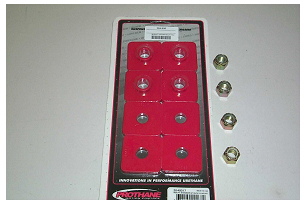
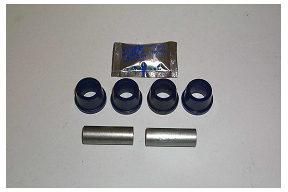
1 - SUPER-FLEX TRUNNION BUSHING KIT
8 - 3/8" SAE GRADE 8 HEX HEAD BOLT
8 - 3/8" LOCKWASHER
4 - 3/8" NUT
4 - 3/8" SAE NYLOC NUT
8 - POLYURETHANE BUSHING
2 - PROTHANE LUBE
4 - 1/2" ID x 1.625" OD WASHER
4 - 1/2" SAE CASTLE NUTS
4 - COTTER PINS
PLEASE NOTE: BOLTS THAT ARE PROVIDED ABOVE ARE THE NON-SHOULDERED TYPE
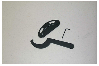
1 - COIL SPRING ADJUSTING
1 - 13mm ALLEN WRENCH
1 - TEMPLATE
The following instructions are over and above those found within the coil-over suspension kit. Also, we recommend following the appropriate instructions, which can be found within various MGB workshop manual publications.
In order to carry out this suspension modification, it is recommended that the crossmember be removed from the vehicle. Install the provided crossmember to body polyurethane mounting pads.
Before removing the crossmember be sure to tighten the upper 1/2" nyloc mounting nuts (4) first. Remember that it is only necessary to remove the lower nuts for crossmember removal.
Once the crossmember is removed and dismantled, attach and position the provided template to the outer shock absorber mounting bolt holes. Using a 1/8" drill bit, drill through the template and through the crossmember material. Change the drill bit to 1/4", then remove template and drill out all the 1/8" holes. Make 2 vertical hacksaw cuts through the crossmember, intersecting at the outer two holes. Grind away enough cross-member material to accommodate the strengthener plate provided within the H003 Kit. The plate can now be welded into position.
NOTE: Please be reminded that British Automotive CAN NOT provide you with the above service.
All polyurethane bushing installation must be "clean fit". The upper trunnion inner bush surfaces and lower wishbone pivots must be free of rust and scale.
All bushings must be inserted in the upper wishbones, lower wishbones and upper trunnions dry. Only the inner portion of the bushings, along with the end faces of these bushings, should be lubricated with the supplied lubricant. Assembly in this manner will ensure that the bushing and the suspension component assembly will rotate around the center pivot as one unit, as they should.
We remind you that British Automotive can supply you with all your additional suspension component needs.
Since this kit has been revised over the earlier kit, you will need to pay attention to the following:
In image P0002742 the super-flex bushing tube(s)are of a pre-determined length. Likewise, in image COIL-OVER SK.jpg spacer tube #6 is also of a pre-determined length.
The problem lies in the fact that both of these parts may need shortening (by machining), or lengthening (by means of spacer washers), depending upon the fitment of the upper arm(s) polyurethane bushings and the upper trunnion bushings.
First, we are concerned with is the prevention of the aforementioned polyurethane bushings from being distorted when the spacer tube #6 is tightened
Using the hardware provided, install the upper wishbone arms to the upper mounting assembly. Lubricate the polyurethane bushings as indicated earlier. Using the old 1/2" nyloc nuts, which you removed during the cross-member removal, fit and tighten. Now measure the inner distance between the front and rear wishbone assemblies at the spacer tube #6 location. This measurement should correspond with that of the spacer. Rectify if needed. When you are satisfied that this has been accomplished, tighten spacer tube hardware.
Remove the old 1/2" nyloc nuts and install the new 1/2" nyloc nuts. You can fully tighten these when the vehicle is on the ground.
Our next area of concern is the correct pre loading of the upper trunnion bushing assembly.
Now measure and record the distance between the upper wishbones at the upper trunnion bolt location holes.
Lubricate the upper trunnion bushing assemblies, as indicated previously, and fully compress into the trunnion. Place the castor-adjusting washers into position. With two castor-adjusting washers each side, the bushing support tube should be approximately inboard by about .020" either side. This amount should give the necessary bushing pre-load.
Make sure to do the final tightening of this item, as well as the upper mounting 1/2" nyloc nuts, and all hardware with the vehicle on the ground.