|
|
BRITISH AUTOMOTIVE |
|
www.mgbmga.com MGTD Articles |
KYB Rear Telescopic Shock Conversion Kit
(Tube Axles Only)
Last Updated - 02/10/10
PRIOR TO INSTALLATION NOTES
When installing telescopic shock absorbers as replacements for the OEM shocks, it is important that the installer understand the nuances with this conversion, especially telescopic shock absorbers that do not have internal bump stops in the design which, is what we will be dealing with in this particular case.
Since, the supplied KYB shock absorbers fall in to this category, it is extremely
important that the unit does not “bottom-out”.
On the MGB, the ideal installed height of the telescopic shock absorber would be one that would have equal amounts of bump displacement and rebound displacement. From the information below, we should be looking at an installed height of 13”. So, before you begin your installation, and with the full weight of the vehicle on the ground, I recommend that you measure the existing distance from the OEM shock pivot arm center to the center of the lower shock link mounting hole, add an additional amount of 2”.
At the same time measure and record the distance between the bump stop rubbers and the bump stop pedestals. Adequate clearance must exist between the bump stop pedestal and the progressive bump stop rubber. Look for approximately 2.5” clearance.
Since, the rear ride height has a direct relationship with the telescopic shock installed height; you may encounter installation difficulties if your rear ride height is too high. This is especially true if you have installed, or contemplating installing, regular arch OEM steel springs. Since, new steel leaf springs invariably “settle” over a relatively short period of time! WAIT until this occurs.
Although rear ride heights can lowered by the conventional method of placing spacer blocks between the axle tubing and upper road spring leaf, you may be limited on the amount by the length of the “U” bolt itself. British Automotive has ½” stackable spacers that fit between the upper spring seating pad and the “U” bolt guide plate. We do not provide longer “U” bolts.
Since, the upper shock mounting is not adjustable, any required increases in the shock absorber installed height can be done by installing British Automotive’s ½’ stackable spacer blocks (see image P0003087) between the lower spring seating pad and the “U” bolt guide plate. However, once again, you may be limited on the amount by the length of the “U” bolt itself. Again, we do not provide longer “U” bolts.
Before installation, we recommend fully compressing the shock absorber, and scribing a line around the periphery of the lower shock body at the shoulder of the upper sleeve. This mark will represent the maximum compressed length of the shock absorber.
When doing the final shock absorber installation, it is more convenient to have the vehicle on car ramps or a hoist with wheels making contact in such a way that the full vehicle weight is exerted over the rear wheels.
Continuing………. Since all mounting hardware is supplied in grade 8 (zinc yellow plated), there may be issues with thread free-run. Before starting your installation, all mating nuts and bolts, excepting locknuts, should be lightly oiled and free-run with their mated part.
Before final installation, it is important that the shock absorber gases be neutralized by fully compressing the shock and letting the shock return to its extended position. Repeat this at least 4 times.
| PART (SPG824) | DIMENSIONS |
| Compressed Length | 10.0" |
| Extended Length | 16.0" |
| Ideal Installed Height | 13.0" |
| Working Length | 6.0" |
| Ideal "Bump" Travel | 3.0" |
| Minimum "Bump" Travel | 2.5" * |
| Ideal "Rebound" Travel | 3.0" |
REMOVE
Using the appropriate MGB workshop manual, proceed and remove OEM shock assemblies, shock absorber links, bottom mounting plates, “U” bolts and bump stop pedestals.
INSTALL
1. Install new upper mounting brackets (use original mounting bolts).
2. Using ½” drill, drill out the center of the bump stop pedestals and press in the 5/16”
Pemn nut inserts from the underside (more on this later in the text).
3. If necessary, install ½” spacer block(s), along with new lower mounting brackets, “U”
bolts and bump stop pedestals per your workshop manual.
NOTE: Install new lower mounting brackets with flange facing downwards.
Having achieved the ideal shock absorber height, or close to it, your shock absorbers are now ready to install. However, your vehicle should now be on car ramps or a hoist as outlined earlier.
4. Install shock absorbers. (Temporarily use regular ½” SAE nut on the bottom mount).
5. Now measure the distance between the bump stop and the bump stop pedestal. * Add
½” to this measurement. This is now your bump travel.
6. Measure the distance between the bottom of the outer shock sleeve and the marked
periphery line on the shock body.
7. The measurement in 6 should be more than what was registered in 5.
Now here comes the important part; how do I rectify a problem if my shock absorber measurement in 6 is less than the measurement in 5?
There are two ways. 1. Decrease the bump stop distance.
or
2. Go back and increase the lower mounting position.
- If your measurement is greater than indicated above, we have available ¼”spacers
that attach to the bump stop pedestals. This is why we had you install the 5/16”
Pemn nuts beforehand. Just for the record, these ¼” spacers are stackable to a
maximum of 4.
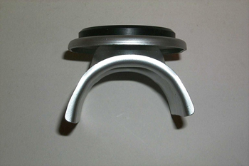
P0003085 below shows a ¼” spacer mounted on top of the bump stop pedestal
- Nobody likes redoing work again. So all I can say is that if you have done your homework, you should not be reading this paragraph. However, should you have to install additional ½” spacer(s), you may have to source longer “U” bolts.
P0003087 below shows these ½” spacer blocks with locating rings.
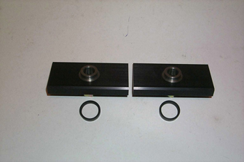 |
| P0003087 |
The final items that we haven’t talked about are the axle check straps.
It may not be possible to have these functioning as they should. This is really not a serious drawback. In the past, we have left them disconnected a number of times, simply letting the shock absorber do this job as per the MGBRV8. However, we do leave them connected at the upper mounting point. Should you need to have the rear axle suspended at any time while working on the rear end, simply reconnect them to the bottom mounting point.
In conclusion, it may not be entire possible to achieve exact installed height, bump stop and rebound measurements, the main criteria is that the shock absorber have enough work length so as to not “Bottom Out”
Thanks to one and all for reading this article.