|
|
BRITISH AUTOMOTIVE |
|
www.mgbmga.com MGTD Articles |
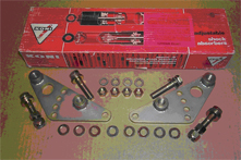
KONI Rear Shock Absorber Kit
Last Updated - 01/31/10
British Automotive designed adjustable upper shock absorber mounting bracket is utilized with your KONI (80-1244SPI) telescopic shock absorber kit. While these shocks are fitted with integral bump stops, it is advisable that the OEM rubber bump stop be retained and active under full bump conditions.
| KONI/KIT | L/H UPPER BRACKET |
 |
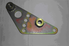 |
| P0004308 | P0004310 |
In P0004310 above, A (Right) is the front mounting boss and B (left) is the rear-mounting boss. The holes are from bottom to top are AB1 (Initial) AB2, AB3 & AB4. You will have the option of working with A or B mounting bosses. If you are working with the B mounting boss, the shock absorber installation angle will be significantly reduced, however, its’ efficiency will be increased. Be sure to check and rectify any interference problems that may exist between the shock body and the right hand rear wheel cylinder brake line. Simple bending of this line is all that should be necessary.
Using mounting boss A will result in an installed angle of between 20 and 25 degrees.
NOTE: If you use this mounting position, it will be necessary to change over
the OEM bottom mounting plate from side to side. Adjustments are in approximately 3/8” increments
Using mounting boss B will result in an installed angle of between 5 and 8 degrees.
NOTE: If you use this mounting position, in general, it will not be necessary to change over these plates. However, this will depend entirely upon your vehicles rear suspension ride height. Adjustments are in approximately 1” increments.
INSTALLATION INSTRUCTIONS
NOTE: In the past, we have provided instructions requiring that the vehicle jack stands be placed, depending upon which operation is being carried out, either under the body, or either under the rear axle tubing. We have reviewed these prior instructions, and concluded that it is more convenient to have the vehicle on car ramps, or a hoist, with the wheels making contact in such a way that the full vehicle weight is exerted over the road wheels.
Remove the shock absorber links from the lower plates.
Remove shock absorbers complete with links.
Using the lower of the 4 mounting holes, install new upper mounting bracket. There is no need to install the lockwashers at this stage, simply hand tighten nuts.
We have found that in the past it is far easier to work with mounting B position first. If this installation proves unsuccessful, then the conventional use of A mounting should be used.
(1)…. Measure the distance from the upper bracket shock absorber mounting stud B to the center of the OEM shock absorber link mounting plate hole.
| PART (80-1244SP1) | DIMENSIONS |
| Compressed Length | 11.1/2" |
| Extended Length | 16.1/4" |
| Working Length | 4.3/4" |
| Ideal Fitted Length | 13.7/8 " |
| Ideal "Bump" Travel | 2.3/4" |
| Ideal "Rebound" Travel | 2.0" |
(2)… Rotate the adjustable upper bracket to the ideal fitted length of 13.7/8” or as near as possible to this length as in (1) above.
(3)… Measure the distance between the bump stop pedestal and the progressive bump stop rubber. This measurement now represents the suspension travel that the rear axle goes through before actual bump stop contact is made.
Hopefully, the amount of distance in (3) will be slightly less than 2.3/4”. Normally, we would like to see ½” bump rubber compression. However, with this shock absorber shorter stroke, this is not possible.
(4)… Install all remaining hardware.
Obviously, using mounting position A instead of mounting position B would give you finer adjustments. However, this would require the changing over the bottom shock absorber mounting brackets from side to side. If you decide to go this route, just follow the instructions outlined for mounting position B. However, use mounting point A as your starting reference.
We have taken the same approach as in the MGBRV8 whereby, there are no axle check straps fitted for controlling axle drop. Instead, the actual Extended/ Length dimension of the shock absorber limit this movement. However, we leave these check straps in position but disconnected at the rear axle-mounting pin. This allows the check straps to be connected whenever the shocks are disconnected and the rear axle has to be held suspended for any other mechanical work.
NOTE: From experience, I know it can be very frustrating changing OEM shocks over to telescopic shocks. Various Vendors actually make no mention of how accurate you have to be with the final installation. Believe me; I have done dozens of these installations, and all I can say is that in the end it is worth the effort.