|
|
BRITISH AUTOMOTIVE |
|
www.mgbmga.com MGTD Articles |
Rear Shock Absorber Kit
Last Updated - 04/01/08
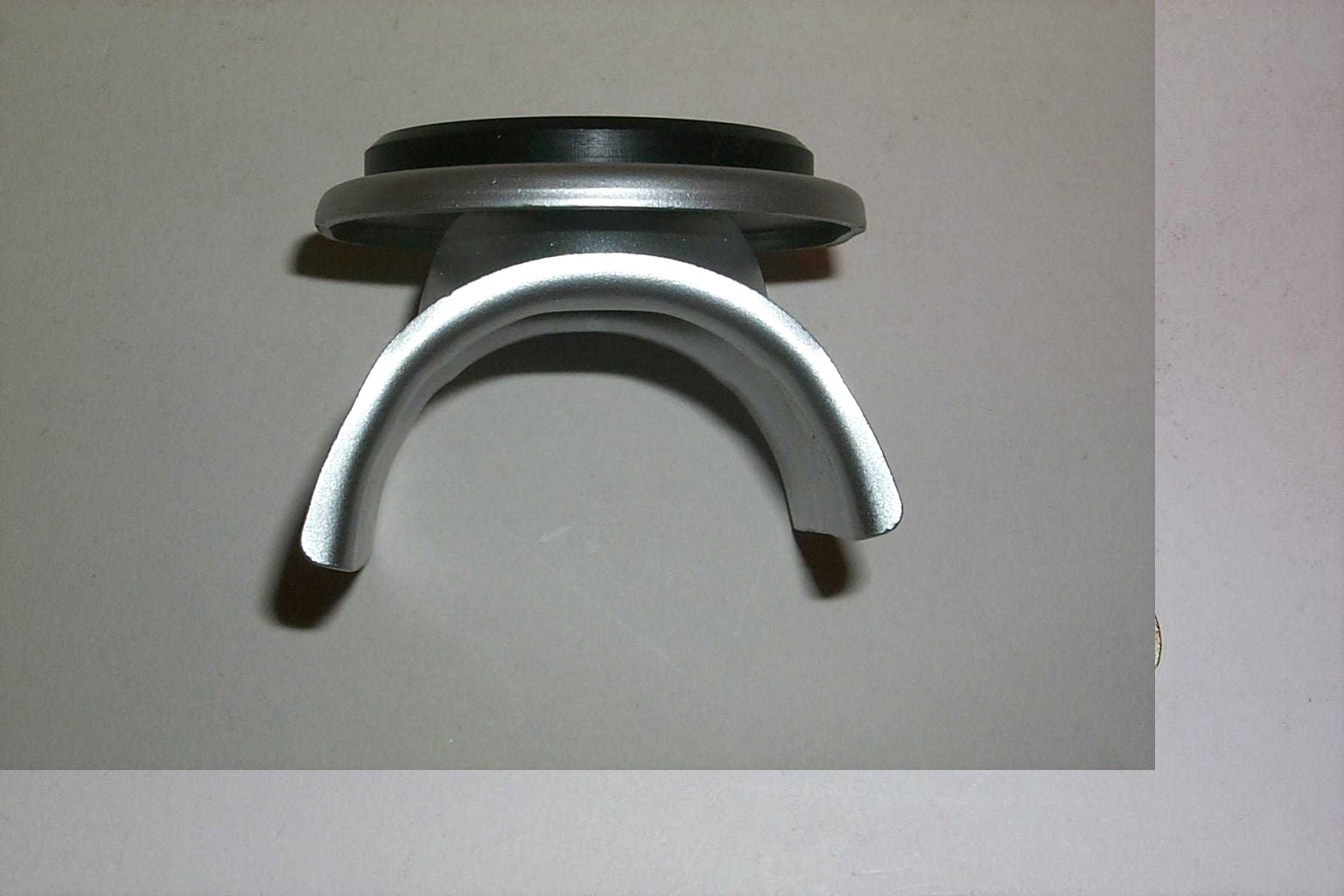
This MGB rear shock absorber kit (PART NO. SHOCK/KITB) has the advantages that in most installations, not all, it does not require the removal and reversal of the lower mounting bracket, which is common on most other kits. With this in mind, we have further redesigned our adjustable upper mounting bracket as seen in image P0003584 below. .
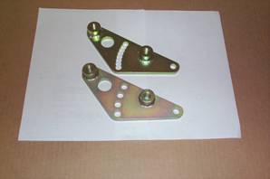
(LEFT HAND SHOWN)
In the image above, the upper mounting bracket, while similar to its predecessor, has been modified to allow the installer more options during the telescopic shock absorber installation process. Within this new design, we have now incorporated eight different mounting positions along with two mounting bosses A (far right) forward mounting boss (front of vehicle) & B (far left) rear mounting boss (rear of vehicle) for a total of sixteen adjustable positions. Working from bottom to top, these adjustment holes are AB1 (initial) AB2, AB3, AB4, AB5, AB6, AB7, AB8 (A adjusts in increments of approximately 1/8”) & (B adjusts in increments of approximately 1/2”). Also, installed angles for mounting boss A between 20 and 25 degrees & mounting boss B between 5 and 8 degrees.
When retaining your OEM shock absorber link bottom mounting plate in the original position i.e. not inverted and switched from side to side, you will be using mounting boss B only. This mounting boss has been offset upwards in the amount of 3.25” which, is greater than the amount (2”) that would be gained by switching the lower mounting plates from side to side. Using this mounting boss will also put the shock absorber in a more vertical position. To this end, it is extremely important that the shock absorber body is not making contact with the brake line. Simple bending of this line is all that is necessary should contact be made.
However, having said the above, inverting and the switching of the lower OEM mounting plate will give more adjustment options due to the ability of being able to use either mounting boss A or B. This is something that you may consider before installing the shock absorbers.
Since, the supplied KYB shock absorbers contain no internal bump stop, it is extremely important that the unit does not “bottom-out”. Before installation, we recommend fully compressing the shock absorber, and scribing a line around the periphery of the lower shock body at the shoulder of the upper sleeve. This mark will represent the maximum compressed length of the shock absorber.
We have reviewed these prior installation instructions, and concluded that before the final installation of the actual shock absorber, it is more convenient to have the vehicle on car ramps or a hoist with wheels making contact in such a way that the full vehicle weight is exerted over the rear wheels.
Continuing………. Because all mounting hardware is supplied in grade 8 (zinc plated), there may be issues with thread free-run. Before starting your installation, all mating nuts and bolts, excepting locknuts, should be lightly oiled and free-run with their mated part. Be sure to lightly oil all hardware before final installation.
Using the appropriate MGB workshop manual, proceed and remove OEM shock assemblies and shock absorber links. If desired, switch lower mounting plates from side to side.
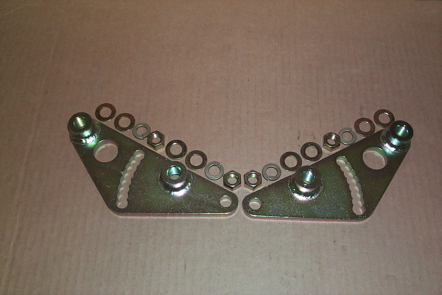
NOTE: This kit contains the following parts only.
2.- Upper shock absorber mounting brackets with hardware kit (retain your OEM mounting bolts).
2.- Gas charged KYB telescopic shock absorbers with mounting hardware kit. (Use the 1/2” SAE regular nuts for initial installation only. Replace with the 1/2” SAE lock nuts
upon final assembly).
 |
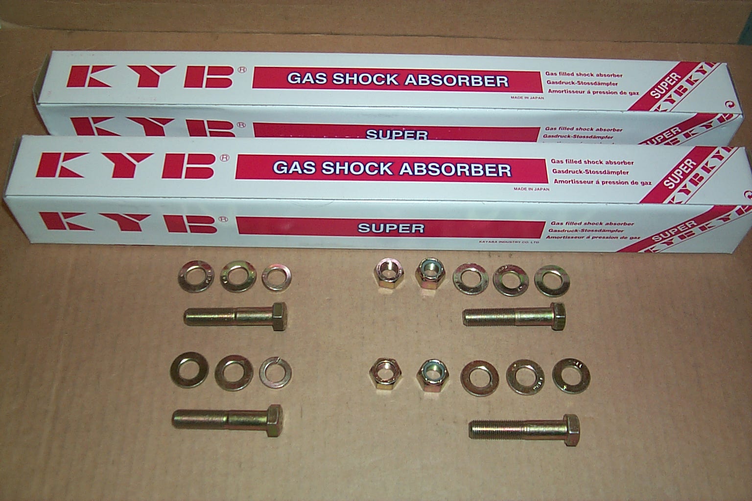 |
| P0003599 | P0003601 |
- Using the AB1 (initial) mounting hole, install new upper mounting brackets. There is no need to install the lockwashers at this stage, simply hand tighten nuts.
- Measure the distance between the rear axle bump stop pedestals and the progressive bump stop rubbers. This distance represents the amount of suspension travel available under “bump” conditions. I consider 2-1/2” to be the minimum allowable. Remember that the rear ride height has a direct relationship with this measurement.
- Temporarily install each shock absorber.
Remember, using mounting boss A will result in an installed angle of between 20 and 25 degrees, and using mounting boss B will result in an installed angle of between 5 and 8 degrees.
NOTE: There is no need to install lower hardware 1/2” SAE nyloc nut until the final (correct) installed height of the shock absorber is known.
Also, before final installation, it is important that the shock absorber gases should be neutralized by fully compressing the shock and letting the shock return to its extended position. Repeat this at least 4 times.
We now refer you to the following information:
| PART (VBPBA1) | DIMENSIONS |
| Compressed Length | 10.0" |
| Extended Length | 16.0" |
| Working Length | 6.0" |
| Ideal "Bump" Travel | 3.0" * |
| Ideal "Rebound" Travel | 3.0" |
Since the shock absorbers are not equipped with internal bump stops, we have included 1/2” compression of the bump rubber stop within this amount, thereby, preventing damage to the shock absorber from “bottoming out”.
In regards to the rebound travel, we have adopted the same approach taken by the MGB RV8 where there are no axle straps fitted to control axle drop. Instead, the actual Extended Length dimensions of the shock absorber limit this movement. However, we leave these check straps in position but disconnected at the rear axle mounting pin. This allows the check straps to be connected whenever the shocks are disconnected and the rear axle has to be suspended for any other mechanical work.
With the multitude of adjustment holes available you should be able to install your shock absorbers so that they do not “bottom-out”. The final check should be made by checking the amount of travel available between the axle bump stop plate and the rubber stop itself, plus ½”. Compare this total against the periphery scribed line on the lower shock absorber body and the bottom of the upper sleeve measurement. Noting that, this measurement should be greater than the recommended aforementioned 2-1/2” plus the 1/2” compression of the rubber.
When you are satisfied that the installation of the shock absorbers is correct, fit upper shock absorber mounting lockwashers and tighten hardware. Install the lower shock absorber mounting 1/2” nyloc nuts; tighten along with the upper shock absorber mounting hardware.
In certain circumstances, especially with the installation of replacement OEM steel springs, excessive distances between the bump stop and bump stop plate will be found. This condition will prevent you from achieving correct shock absorber installed heights.
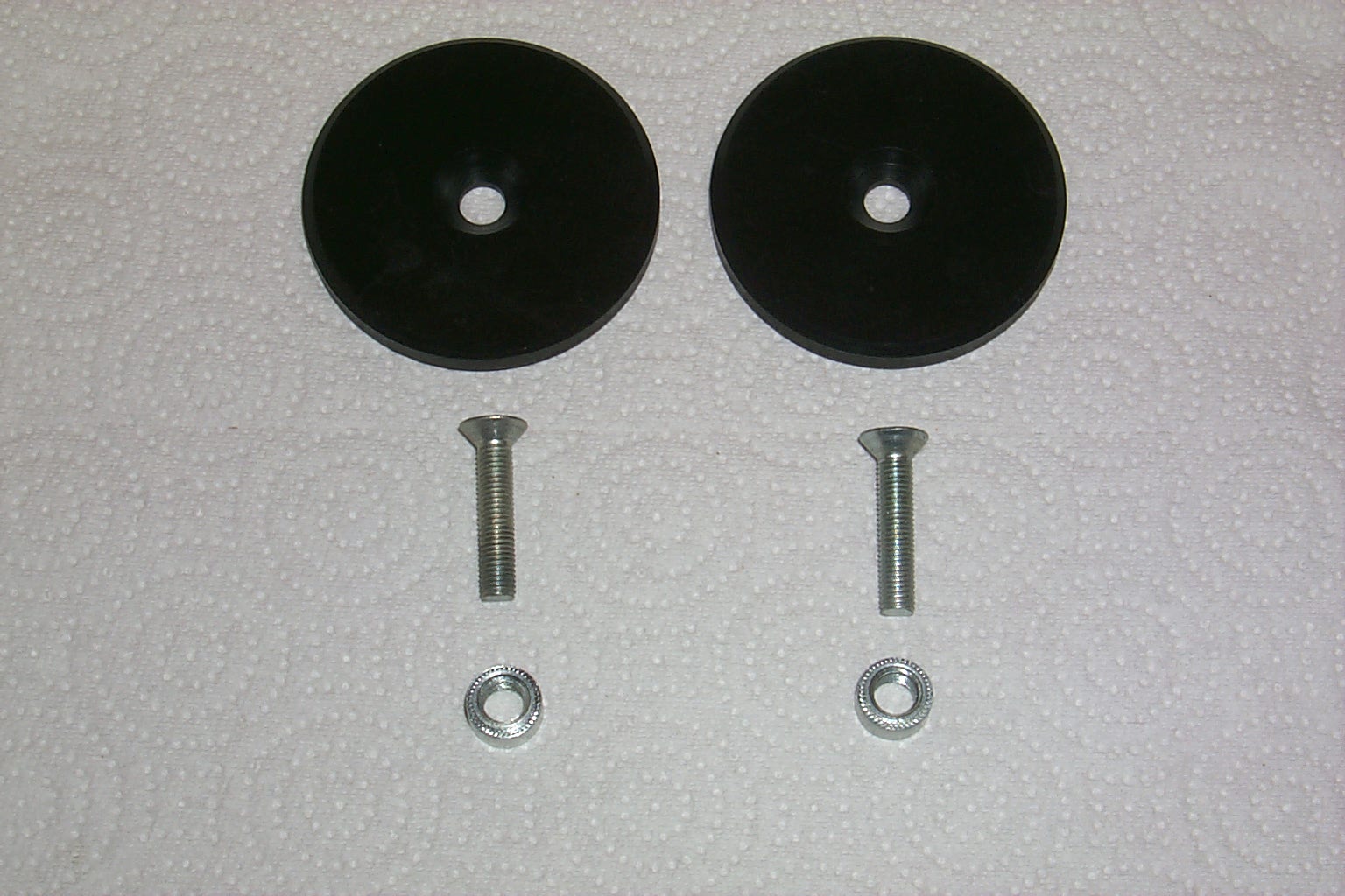
The solution to this problem is to install our 1/4” stackable bump stop plate spacers, which can be simply removed as the new springs “settle”. This method, in our opinion, is preferable than using rear axle lowering blocks. Be prepared for this eventuality by modifying your bump stop plates beforehand.
- Using 1/2” drill bit, drill out the center of the bump stop plates.
- From underneath, press in 5/16” SAE pem nuts.
Ok, now back to the shock absorber installation.
- Determine the amount of spacers that you are going to require.
- Cut the securing screw to the correct length. 1 spacer = ¾” 2 spacers = 1” etc.
- Clean and oil thread.
- Install screw. (Be sure base of screw is not contacting axle tube).
Obviously, as the springs “settle” premature bump contact will be made. Therefore, it is recommended, once you hit the road, that you occasionally measure the distance from the underside of the chrome strip to the center of the road wheel for ride height changes. Remove spacer(s) as required.
 |
 |
| P0003918 | P0003085 |