|
|
BRITISH AUTOMOTIVE |
|
www.mgbmga.com MGTD Articles |
MGB ALL SYNCHROMESH TRANSMISSION CONVERSION FOR THE MGA
(MGA4)
MGB ALL
SYNCHROMESH TRANSMISSION CONVERSION FOR THE MGA
The following articles deal with the replacement of the existing OEM transmission with the MGB 68-> all synchromesh transmission with, or without, overdrive.
We have spent a considerable amount of time and $s to bring you this professional conversion. British Automotive can supply you with the below parts. You must source items that are not listed, such as, engine, engine backplate, flywheel, starter motor, driveshaft, transmission/overdrive and complete handbrake assembly.
The most noticeable part of this conversion is the new and slightly larger fiberglass transmission cover/tunnel, which fits directly on top of the floorboards, unlike the original arrangement.
TRANSMISSION MOUNT
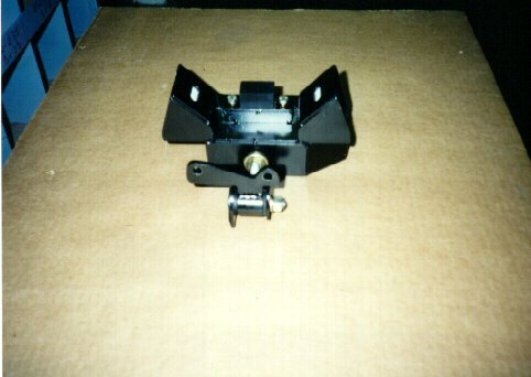
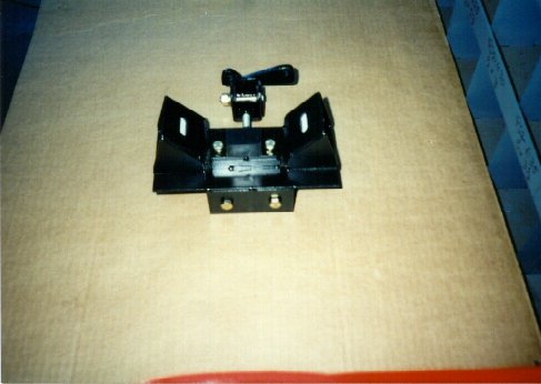
A completely new assembly, with stabilizer rod, is utilized. The stabilizer rod prevents the forward movement of the engine/transmission unit under heavy braking. This Trans mount assembly fits over and is bolted directly to the existing crossmember, however, this requires the removal and grinding away of the original Trans mounting eye brackets.
TRANSMISSION COVER/TUNNEL
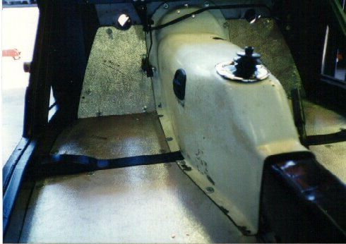
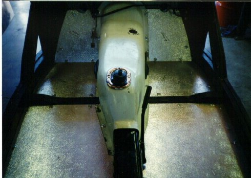
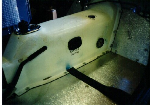
As previously mentioned, this fiberglass component is slightly larger than the original assembly and consequently, will need to be recarpeted. Provisions have been made for access to the following:
1. Transmission dipstick/filler (68-74).
2. Transmission side check/filler (74.5->).
3. Overdrive inhibitor switch.
4. Back-up light switch (if so desired).
The shift lever boot and chrome retaining ring, with securing screws, are provided with the fiberglass cover/tunnel, as are the rubber blanking plugs for the above access holes. No modifications are required to the throttle cross shaft assembly. However, the existing guide channels for the original cover/tunnel must be removed.
FLOORBOARDS
We can supply you with this kit, however, you must order the 1500 low starter style kit. This will allow you cut out the passengers' toeboard starter bendix relief more accurately.
HANDBRAKE ADAPTOR
We adapt the handbrake assembly, complete with ratchet plate, from the 1977,78,79 or 80 MGB models. The handbrake assembly has a peculiar angular design and works well in between the fiberglass cover/tunnel and the passenger’s seat. An adapter is supplied separately to allow the fitting of this item. Your original handbrake cable can be retained. Adjustment, beyond the normal adjustment procedure, can be accomplished by drilling (rearward) an additional cable trunnion attachment hole.
SPEEDOMETER CABLE
If you are using a non-overdrive transmission, you can retain your original cable (5’6”). However, It is advisable to install a speedometer angle drive unit as fitted to the MGB. In the event of the Speedo head seizing up, fitting this item will prevent damage to the gearbox mainshaft speedometer nylon drive (depends on which year transmission you fit) and the driven gear.
Overdrive transmissions require a longer speedometer cable (6’6”). Unfortunately, the only readily available cable is part # GSD169 (Moss part # 331-430 which is approximately 6ft long. This cable will work. However, the radius is a little on the tight side. Due to the tight confines of the overdrive unit within the fiberglass cover/tunnel, no speedometer angle drive can be fitted.
SPEEDOMETER HEAD
It will be necessary to service and recalibrate this item. To work out the new revolutions per mile move the vehicle thru 52’9.5” (transmission and cable installed) and count the number inner cable revolutions. Multiply this number by 100 for your new total.
TACHOMETER (5 MAIN BRG ENGINE)
Use the MGB tachometer 63-67 with the associated metal loop bracket and insulator. Install ignition bulb fixture part # CAB301 (54364381) or Moss part # 158-330. Cut and join the original white ignition wire and field wire to this fixture. Cut the existing ignition supply white wire at the fuse box and splice in a new white 16 gauge wire. Direct this wire to, and loop thru, the tachometer insulator (see Moss MGB Catalog MGB-12 for a detailed description) then on to the ignition coil.
DRIVESHAFT ASSEMBLY
Due to the difference in transmission lengths, your new driveshaft flange to flange length will be 32.5”. Original style sliding yoke type driveshafts will have to be updated to the later flange style. The MGA flange style can be shortened to this length. A new driveshaft for the MGB 63-67 roadster (with overdrive) length 32” approx is available under part # 268-100. You could also use any of the remaining MGB driveshafts, rebuild and lengthen accordingly.
MGA AND MGB 3 MAIN BEARING ENGINES
Replace the MGA engine backplate with the MGB 18G 18GA & 18GB style. Attach the backplate to your all synchro transmission, then drill and tap the upper starter-mounting hole to 3/8” USS. (Use 3/8” x 1.3/4” bolt with lockwasher). Next use a 3/8” drill bit and drill a lower starter motor mounting bolt relief indent in the transmission flange to a depth of 1/4”. Remove backplate and helicoil the bottom starter mounting bolt hole to 3/8” USS, (the existing hole size is convenient, use 3/8” x 1” bolt with lockwasher). Additional hardware required to attach the transmission to the engine backplate 6- 5/16” x 2.3/4” SAE bolts with nuts and lockwashers.
You have several ways to solve this next problem, which of course is, getting the transmission input shaft to mate with the crankshaft pilot bushing. First, let us proceed and assume that you are in the engine rebuilding stage and that the crankshaft is out and ready for regrinding, if necessary. Have the crankshaft pilot bushing bore counterbored to a depth of 1.5” to 1.625” and 1.123” diameter. Due to small variations in pilot bushing OD’s, be sure to supply the machine shop with the actual bushing you are going to use (part # 22H1416, Moss # 330-415, as used on the 18V crankshafts). Be sure to let your new pilot bushing soak in 10W oil for several days or weeks. Longer is better.
Alternatively, we could remove the transmission input shaft and have it machined to the following dimensions .6215”-.622” OD to a total length of 1.5” to 1.625”. The MGA/MGB pilot bushing dimensions are .814” OD x .6875” length x .625”-.626” ID. for a working clearance of approx .003”.
Personally, I would take the old transmission input shaft or transmission assembly to the machine shop for custom sizing.
MGB 5 MAIN BEARING ENGINE (BENDIX STARTER)
We prefer to use the MGA starter motor (bendix OD 1.32" length 5.375") to the MGB style (bendix 2" length 6.375"). There will be less intrusion into the interior with the MGA starter motor. Another point is the size of the starter motor bendix relief hole that has to be made in the transmission housing. MGA 2.125" MGB 2.875". Use your original starter motor battery cable.
MGB 5 MAIN BEARING ENGINE (PRE-ENGAGE STARTER MOTOR)
We will assume that you are going to retain the original 5 main bearing engine backplate, flywheel assembly and starter motor. We still recommend that you install the upper (2) transmission mounting flange studs. The only other item would be to make up a new 15” starter lead using #4 gauge battery cable (C52425/BLK) with terminal eyes NOB925 (5/16” eyes) for a total length of 17”(eye to eye).
STARTER MOTOR BENDIX COVER
A fiberglass bendix cover, similar to the one found on the 1600 MGA OEM transmission tunnel, is available separately.
INSTALLATION PROCEDURES
We will start with the presumption that the engine, transmission, Trans cover/tunnel (front and rear sections), driveshaft, floorboards, including the toeboards have all been previously removed from the vehicle.
Before installing the engine and transmission units carry out the following:
1. Cut the two existing transmission mounting eye brackets from the crossmember, I prefer to cut them in a way that will allow their future attachment, if so desired. Also, remove the transmission cover guide channels. Grind and smooth all welding beads on the crossmember assembly.
2. Using a 5/16” helicoil tap, tap the two upper holes on the transmission bell housing where they attach to the engine backplate, locktite and install studs (2). (Part # 328-997).
3. If you are installing a transmission with overdrive, it will be necessary to grind away the excess overdrive casing material in the area of the speedometer pinion drive gear abutment. You will see a sharp and protruding abutment, so, simply grind away and contour into a shallow radius.
I prefer to place the transmission into the frame first, then install the engine. If you have not removed the metal firewall you will have to remove the steering rack mounting bolts and the steering shaft u-joint pinch bolt, this will then allow you to pull the steering rack assembly forward and clear the crankshaft front pulley. Bolt-up the transmission and tighten engine mounts.
Transmission Mount Installation
Jack up the engine/transmission unit and slide the transmission mount/bracket assembly, without the stabilizer bar, over the cross tubing. Leave the nuts that attach the actual rubber mounts to the slotted bracket loose. Lower the engine/transmission unit down and install the 4 bolts and lockwashers that hold the rubber mounts to the transmission case. Tighten the slotted bracket nuts. Install the stabilizer bar assembly, with the large eye opening facing the passengers' side.
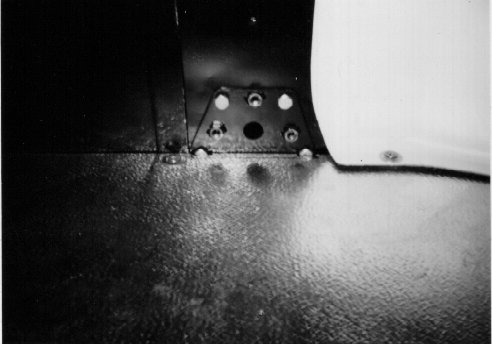
Metal Firewall Modifications

To allow for clearance between the transmission bell housing and the metal firewall, along with the fitting of the cover/tunnel, you will need to modify the above as follows:
Starting at the drivers side lower outer welded nut center, measure 6”, directly inwards and in line, center punch this location. From the passengers side measure 6.3/4” in the same manner. Drill (3/8”) these new locations and install 1/4” 20 TPI nutserts. Using the original 3 factory welded nuts as a guide, scribe a line following the periphery of these nuts and drill a series of 1/8” holes as close as possible together. Using pliers, or channel locks, twist off the excess material. Use a die grinder and contour the new opening. If you have already previously removed the metal firewall, refit with new packing strip, as found in body packing set part # 281-778.
Handbrake Adapter Plate
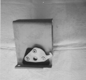
The portion of the original transmission cover/tunnel, which the handbrake was originally attached to, must be separated from the main structure at a point approx 1/4” forward from the center of the spot welds. File all sharp edges smooth.
Separate the 2 cross braces from this section, place and centralize the adapter plate, in relation, to the original handbrake lever pivot hole. Mark and drill 4- 21/64” holes. Attach the adapter plate along with the
cross braces, use your original mounting hardware with the provided special cutoff 5/16”x 3/4” SAE bolt at the drivers side lower front hole, positioning the cut off portion upwards so as to prevent interference with new transmission cover/tunnel seating flange.
Do not install the handbrake ratchet plate at this time, otherwise, it will interfere with the cover/tunnel fitment. Installation can be carried out later. We have provided the hardware, including 5/16” SAE flat washers, for this and you will notice two different lengths of securing screws, this will allow you to space out the handbrake lever assembly to allow for recarpeting later.
At this stage it will be easier to install the driveshaft assembly, simply slide this crossbrace section down the driveshaft to expose the front flange.
Floorboards and Cover/Tunnel
If you are using the bendix type starter motor, install the OEM MGA type. You could use the MGB type, however, the larger size bendix presents clearance problems and also intrudes into the passengers toeboard more than the smaller MGA type bendix. I now normally transfer the outline of the passengers' toeboard onto an appropriate size of stiff cardboard. Cut out and lay this template into position, cutting away the relief for starter bendix as you go. When you are satisfied that you have sufficient clearance, transfer the template back on to the toeboard and cut out the starter bendix relief area. Remove starter motor. Install your floorboard kit, make sure to install the backboard first, followed by the rear section of the OEM tunnel, joining this portion to the crossbrace section as you proceed.
Upon final assembly both the drivers and passengers toeboards should clear the transmission housing. Remove excess toeboard material in this area.
1. Install (2) “T” nuts (1/4” 20) on the drivers and passengers toeboards (inner lower holes).
2. Place the fiberglass transmission cover/tunnel into position and mark the securing flanges at a point where crossmember relief will be needed. Remember to allow enough width because as the cover begins to seat it will have a tendency to move rearwards. Trim these cutouts until the cover can be seated without interfering with the crossmember. Remove cover/tunnel and cut out the necessary access holes, excluding gearshift aperture.
3. With cover/tunnel placed into position, start at the drivers' side and mark the following holes: Toeboard (2) Heelboard (2) and Mainboard (1). Utilize the original hole adjacent to the front lower bolt head that has been relief cut- ignore the (2) forward holes for the moment. Centralize all these marks in the middle of the securing flange.
4. Remove cover/tunnel and drill marked holes with 9/32” drill bit (this avoids tearing of the fiberglass material) then enlarge with a 3/8” round file or T-handle reamer.
5. Refit cover/tunnel and install (5) screws and washers. Centralize and tighten.
6. Mark the (2) remaining cover/tunnel drivers side main floorboard hole locations on the securing flange. Equally space, and be sure that you have made provisions at the forward floorboard hole, this will allow the securing screw to clear the metal seating flange. Centralize and drill these locations with 1/8” drill thru the flange and floorboard.
7. Remove cover/tunnel, drill (9/32”) and file out these two remaining flange holes.
8. Drill (3/8”) out the two 1/8” pilot holes in the drivers' main floorboard. Install (2) “T” nuts (1/4” 20).
9. Refit cover/tunnel and install the (7) screws and washers, finger tighten only.
Due to the clearance problems with the all synchro Trans overdrive unit, this next operation needs to be carefully undertaken so as to allow adequate clearance between the overdrive speedometer adapter boss (see introduction section) and the adjacent cover area. Also remember we still have not yet secured the Trans/bracket to the crossmember, so, any final clearance needed could be achieved by prying the bracket assembly towards the drivers side. However, be sure that the driveshaft front flange clears the inner part of the fiberglass cover on the passengers' side.
10. Push the cover assembly across from the driver’s side and then tighten the (7) cover securing screws on the driver’s sideboards. Starting at the uppermost inner passenger’s side toeboard, mark the position for the hole, (from and thru the back of the metal toeboard/firewall).
11. Remove cover and drill (9/32”) marked position making sure you are well centralized on the securing flange. Any offset required to achieve this can be accomplished with the use of a 3/8” round file.
12. Reinstall cover and install the (8) screws and washers now accounted for. Mark and centralize (3) holes on the passenger’s toeboard (1) and main floorboard (2). Prior to instruction 15 make sure to leave adequate clearance as outlined in the above paragraph.
13. Remove cover and proceed to drill out and file these holes.
14. Reinstall cover assembly and secure the (11) screws and washers now accounted for. Using driver’s side heelboard as reference equally space and mark the two remaining holes on the cover-securing flange. Drill (1/8”) thru securing flange into passenger’s heelboard.
15. Remove cover assembly. Drill and file as previously outlined. Also, at the same time, drill (3/8”) thru passenger’s heelboard and install (2) “T” nuts, secure with (6) brass screws.
16. Install cover and secure the (13) screws and washers now accounted for.
17. Our original instructions: Mark and drill (1/8”) thru upper L/H and R/H corners of the cover/tunnel (into and thru the metal firewall) may or may not be possible. You will see what I mean when you attempt this.
18. Note the amount of material that will be necessary to pack the area as mentioned above, as well as the top portions of the toeboards and the rear cover/tunnel upper rear aperture
19. Remove cover/tunnel and proceed to drill and file out these 2 remaining holes.
20. Drill (3/8”) the 2 1/8” pilot holes in the metal firewall and install nutserts 1/4” 20TPI.
21A. Tape over the transmission gearshift lever base. This will stop the ingress of fiberglass material when operation #23 is carried out.
21.Cut and lay the provided stripping into position (toeboards, heelboards and main boards). Mark the appropriate screw holes on the stripping, then use a hole punch to punch out these holes.
22. Install cover and lightly secure with the (13) screws and washers now accounted for.
23. Using the gearshift boot as reference (short offset section rearward), mark pilot hole for gearshift lever. Drill and file out this hole until gearshift lever can be passed thru. The gearshift lever may not be central at this time, so, continue to enlarge the hole until centralized. From here you can remove enough fiberglass material so as to be able to allow full gear selection movement of the gear lever. We recommend that the gear shift lever be shorten by 2.5”and rethread. (3/8”USS).
24. Position and centralize gearshift boot and chrome retaining ring. Carefully mark and drill (9/32”) (4) holes and install (4) nutserts (10 24TPI).
At this stage, if you are satisfied with the fitment of the cover, and sufficient clearance exists between the cover and the overdrive unit, and that there is also sufficient clearance between the driveshaft front flange and the inside of the cover on the passengers side, proceed with #25.
25. Remove chrome retaining ring, gearshift boot and gearshift lever assembly, followed by the cover/tunnel (upon final assembly lay the gearshift boot on top of the cover- don’t try and place the lip between the flange).
26. Using a small chuck sized electric or air drill, drill (21/64” bullit tip) the (2) pilot holes on the Trans/bracket, then install (2) 5/16” X 2.3/4” SAE bolts with lockwashers and nuts.
27. Fit speedometer cable into position. On the overdrive transmission, route the cable alongside the transmission mount bracket within the cover securing flange bolt holes.
28. Cut the provided spacer packing material to the lengths determined previously. Apply contact cement (not supplied by British Automotive) to the material and to the upper portion of the cover, this also applies to the rear cover upper aperture. Remove driver and passenger toeboards and apply contact cement in the same manner.
29. Reinstall cover, proceeding to fit the (15) securing screws and washers in the order that has been outlined in these instructions. Using a medium size awl you can access the upper (2) forward cover securing flange holes. Do not overtighten. If you are carpeting the entire cover, you may want to leave the carpet unglued in the area of the securing flange for future access. Don’t forget to leave a flap in the carpet for transmission oil level checking and filling, this also applies if you have installed an overdrive transmission.
30. Install handbrake ratchet plate, spacing out as previously outlined.
be sure that the securing screws do not bottom out.
31. Install modified gearshift lever along with anti-rattle bush, securing plate, 3 special bolts and washers.
32. Fit gearshift boot, securing nut and gearshift knob.
The installation of the MGA or MGB 3/5 main bearing engines, fitted with the bendix style starter motor, require the following additional instructions.
Reinstall starter motor and relieve the cover flange material that in all probability will be interfering with the bendix. Lay the new fiberglass bendix cover into position, line up with and use the flange retaining screw immediately below the cut out. Drill hole and file to size. Refit bendix cover and secure with washer and retaining screw. Drill (1/8”) 2 remaining holes, (1 directly above existing screw and 1 in the center of the bendix cover rite hand flange *) into and thru the toeboard. The OEM late 1500 and 1600 passenger toeboards had an original “T” nut in this position *. Use one of your original floorboard screws and washer for this application. Aftermarket passenger toeboards do not have a “T” nut prefitted. Remove bendix cover and drill and file out these two holes. Drill (9/32”) the 2 pilot holes in the toeboard and insert “T” nuts where required, secure with provided brass screws. Install bendix cover using an appropriate sealer.
Driveshaft Angle
With the fitment of the all-synchromesh transmission (overdrive or non-overdrive), the installed angle of the driveshaft will be increased significantly, this will be more apparent with the installation of the overdrive transmission. Don’t panic, wait until your vehicle is completely finished and ready for the road. Driveshaft installed angles vary with rear vehicle ride heights. We are trying to get some technical information on what constitutes excessive installed driveshaft angles. Presently, we are running with + 3 to + 4 degrees. If necessary you can lower your vehicle rear ride height with the use of 1/2” stackable blocks, and by doing this, you will be effectively reducing the installed driveline angle.
Finally, we have put this kit together, in a way, which requires a minimal amount of skill, tools and average ability. We have avoided the need for major fabrication, which we hope will be of advantage to you the customer.
PARTS LIST
| Qty | P/N | Description |
|---|---|---|
| 1 | AHH5325/CG | Fiberglass Transmission Cover |
| 4 | DOR701-931 | Nutsert Kit 1/4" 20 |
| 1 | 862-107 | 5/16" x 3/4" SAE bolt(special head) |
| 1 | 14B630 | Blanking Grommet (Oval) |
| 1 | AHH6507 | Blanking Grommet (Round) |
| 1 | AHH6486 | Chrome Finisher |
| 1 | AHH 7170 | Gearshift Boot |
| 4 | OHPS102434 | Securing Screw |
| 1 | DOR701-930 | Nutsert Kit 10/24" |
| 1 | 249-738 | Beading Seal |
| 1 | NPN | 40" Seal |
| 5 | CPZ416/SS | Flange Screw |
| 15 | 64401 | Flange Screw Washer |
| 6 | TNZ1420 | "T" Nut 1/4" 20 |
| 20 | FHMPZ14201 | Securing Screw (Cut to length) |
| 1 | H/B.ADAPTR | Adapter Handbrake Assembly |
| TOTAL PRICE $244.35 COMPONENT WEIGHT 13LBS | ||
| 1 | BENDIX/COVER | Fiberglass Starter Bendix Cover(with hardware) |
| PRICE $69.95 COMPONENT WEIGHT 1LB | ||
| 1 | MGA/BRKT | Transmission Bolt in Bracket with Stabilizer |
| PRICE $292.50 COMPONENT WEIGHT 5LBS | ||
ADDITTIONAL PARTS AND PRICES
| Qty | P/N | Description |
|---|---|---|
| 1 | 456-045 | 1500 Floorboard Set (to C61503) |
| 1 | 456-955 | 1500 Floorboard Set (From C61504) |
| 1600 Floorboard Set | ||
| PRICE $161.96 COMPONENT WEIGHT 24 LBS | ||
| 1 | 323-968 | Floorboard Screw and Washer Set |
| PRICE $44.96 | ||
| 1 | 281-778 | Body Packing Set |
| PRICE $62.96 | ||
| 1 | 331-430 | Speedometer Cable |
| PRICE $17.55 | ||
| 1 | 268-100 | Driveshaft 32" (Approx) |
| PRICE $164.95 | ||
NOTE: COMPONENTS NOT LISTED HERE CAN BE FOUND IN YOUR CURRENT MOSS
MOTORS MGB OR MGA PARTS CATALOGS
REMEMBER WE DISCOUNT 10% FROM CURRENT MOSS MOTORS LIST PRICES
PRICES SUBJECT TO CHANGE WITHOUT NOTICE